5.1.6 Tool I/O
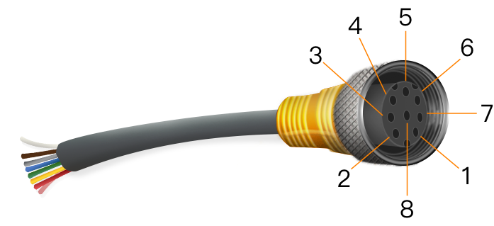
The end of robot comes with an 8-pin connector that provides power supply and control signals for the end tooling (e.g. a gripper). As shown below, you can configure 4 channels of digital I/O via pins 3/4/5/7, and analog input via pins 6/8 with an analog voltage range of 0~10 V; the pin 2 can be configured with 0 V, 12 V and 24 V.

On [Tool I/O] page, you can set the tool I/O control mode, power voltage and digital I/O communication direction. See "5.1.2 I/O Setup" for the function settings of each tool I/O port; see "7.1 Robot" for the monitoring of I/O port status.
- I/O Interface Control: Select the control mode of tool I/O, allowing you to switch between user control and AuboCap control.
- Tool I/O Configuration: Set the voltage output and communication direction of the tool I/O port.
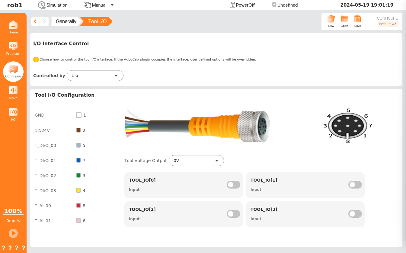
- Controlled by: Control the switching of tool I/O port.
Tool Voltage Output: Set the output voltage when the tool digital I/O port is used as the output port. It is recommended that users configure once before each use.

 : When the digital tool I/O port is in status, the port serves as an input port; when the digital toll I/O port is in status, the port serves as an output port.