2.1 Introduction to GUI
The AUBO SCOPE's GUI consists of the following:
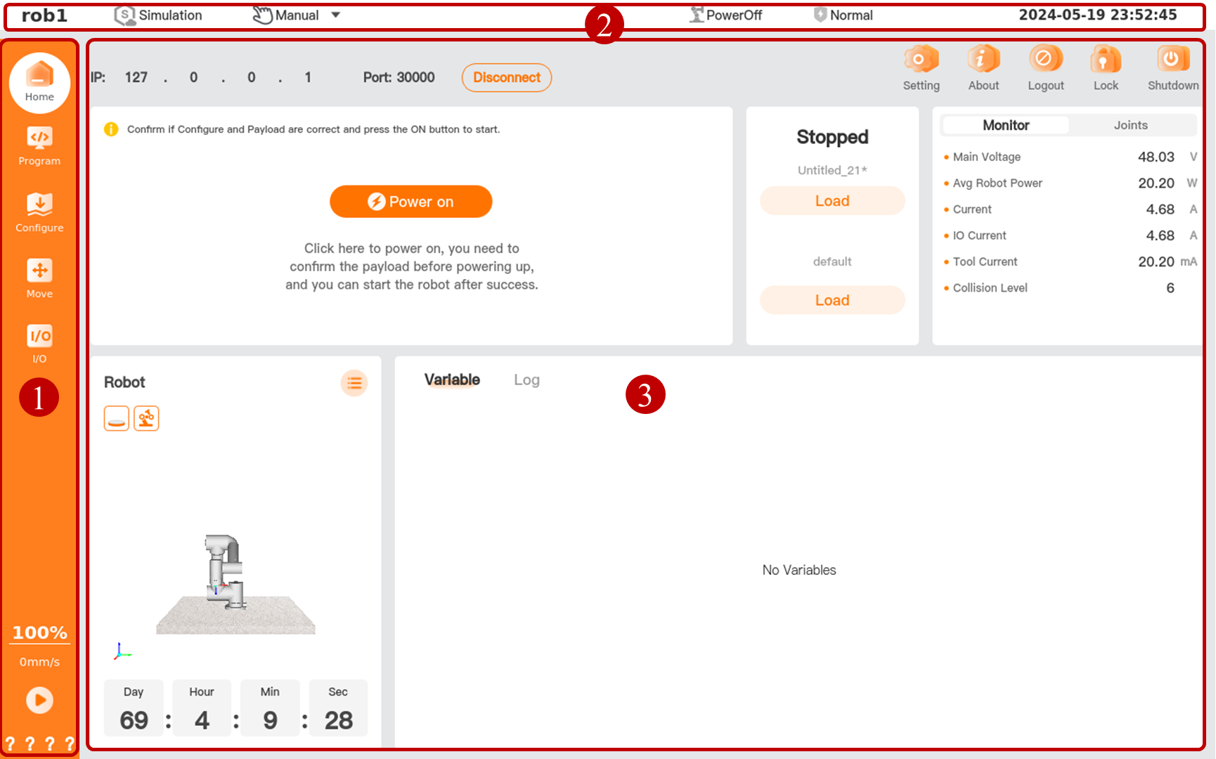
| No. | Name | Description |
|---|---|---|
| 1 | Menu bar | The upper part of the menu bar contains function menus including: Home, Program, Configure, Move, and I/O. The lower part contains program menus including speed, run, safety parameter. |
| 2 | Status bar | The top status bar is always at the top of the interface while the software is running. |
| 3 | User interface | The user interface provides different views for managing and monitoring robot under different function menus, allowing you to control the robot easily and flexibly. |
1. Function menus
| Icon | Name | Description |
|---|---|---|
| Home | Display basic information and program progress of the robot. For more information about "Home", see 3. Home. |
|
| Program | Create or modify a robot program. For more information about "Program", see 4. Program. |
|
| Configure | Configure AUBO robot and external devices. For more information about "Configure", see 5. Configure. |
|
| Move | Control or adjust the movement of AUBO robot. For more information about "Move", see 6. Move. |
|
| I/O | Monitor or set real-time input and output information for controller. For more information about "I/O", see 7. I/O. |
2. Program menus
| Icon | Name | Description |
|---|---|---|
| Speed | Display the current movement speed and the maximum movement speed.
Tap to pop up the [Speed Bar] * The movement speed can be set within 1% ~ 100% (integers only) with a step of 1%. |
|
| Run/Resume Stop Pause Step |
Program Run/Resume/Stop/Step/Pause button.
* Only when all the nodes in the program tree comply with the predefined logic, that is, there are no nodes highlighted in yellow in the program tree, can you use the [Run] button to run the program. |
|
| Safety parameter | Display a four-digit hexadecimal security check code. If the parameters in "Configure > Safety" change, the system will update the check code.
* Before the system is powered on, no safety parameters are accessible to the software, and question marks are displayed here. * Tap here to view details of safety parameters. |
3. Top status bar

| No. | Name | Description |
|---|---|---|
| 1 | Name of robot | Display the name of currently connected robots. |
| 2 | Simulation | Simulation button, for switching the program running between the simulation robot and the real robot. When you turn on the Simulation button, the color of the simulation icon changes, and the system enters the simulation mode.
*For details about simulation mode, see 2.5 Simulation mode. |
| 3 | Mode switch | Mode Switch button, for selecting the mode among Manual, Auto, Link and Local.
* For details about each mode, see 2.2 Operational mode. * Before mode switching, please set the "Mode password" first. See 8.2.1 Classic mode for details. . |
| 4 | Robot status | Display the current robot status. including PowerOff, Booting, PowerOn, Idle, BrakeReleasing, Running, etc. |
| 5 | Safety status | Display the current system status, including Undefined, Normal, and etc. |
| 6 | Date | Display the current date of controller. |