4.3.1 Move
The [Move] node, allows you to add a waypoint for movement of the robot, and set the shared parameters of other nodes under the node.
Move type
The robot can move in three modes: MoveJ, MoveL and MoveS.
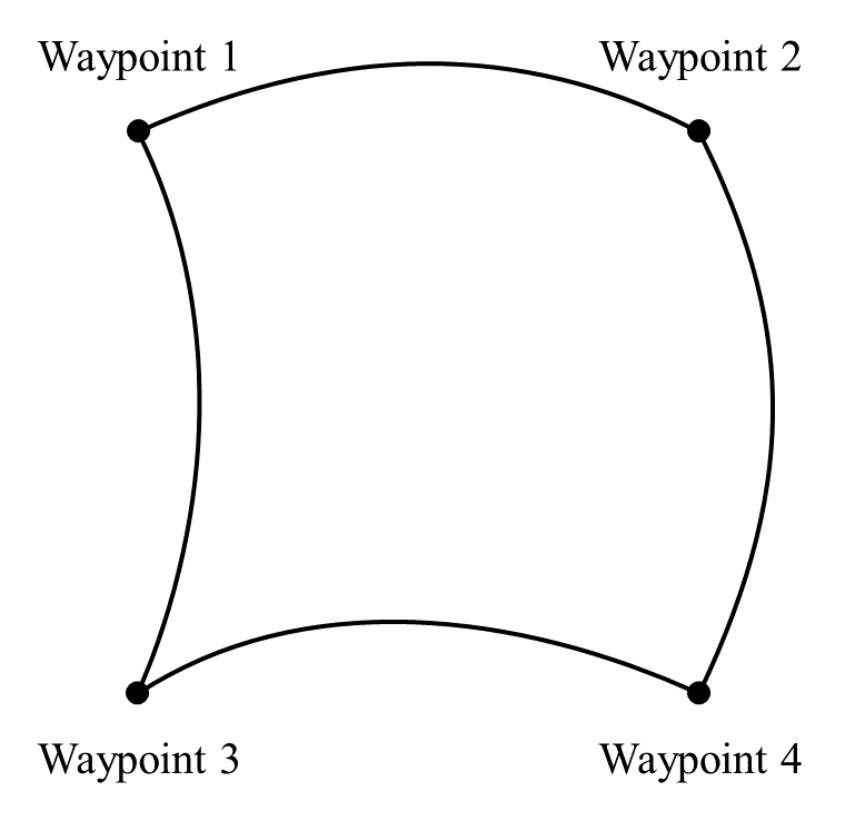
MoveJ refers to the movement of the robot by controlling its joint. MoveJ provides a curved path for the TCP. If you want the robot to move between waypoints quickly, regardless of the movement path of TCP between these waypoints, you’d better to select MoveJ. MoveJ is suitable for movement in the fastest way in a sufficiently wide environment. This motion mode is shown in the figure below.
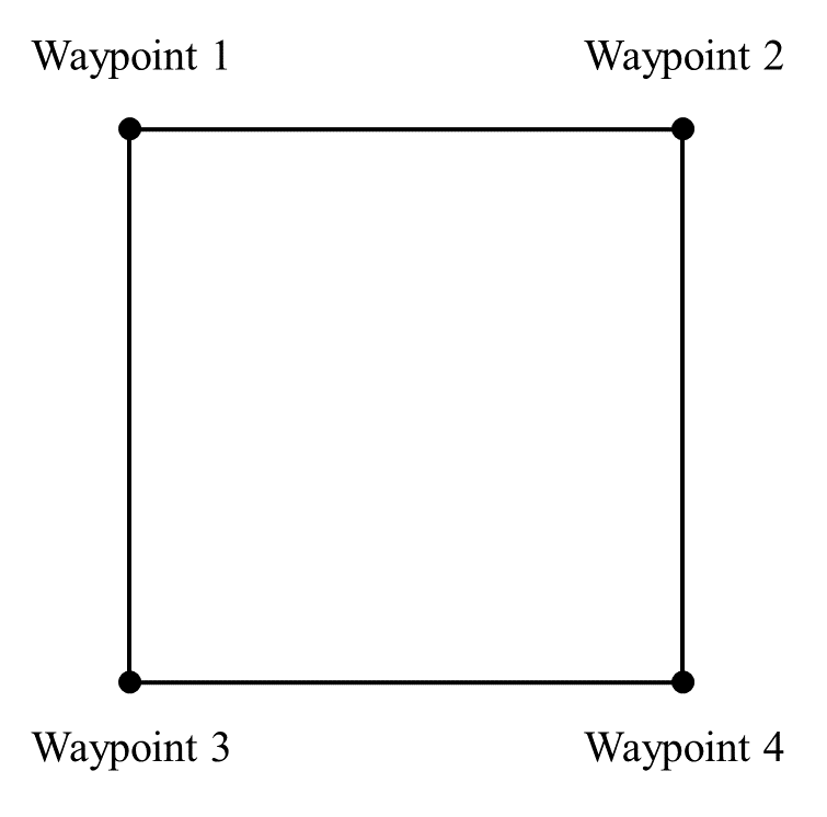
MoveL refers to the movement of the TCP of the robot in a linear way to the target waypoint. This means that each joint will move in a more complex way to keep the TCP on a straight path, and whether the maximum tool speed can be reached and maintained depends on the linear displacement and maximum acceleration parameters. This motion mode is shown in the figure below.
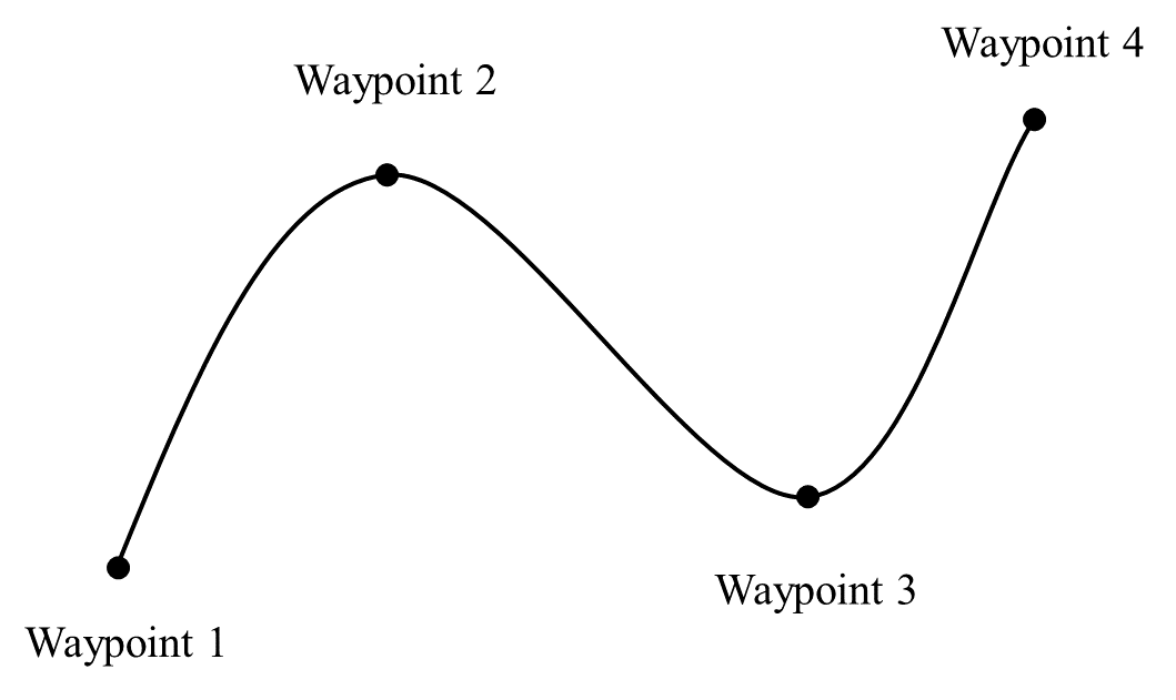
MoveS refers to the smooth movement of the robot through all given waypoints at a constant speed according to a spline curve path based on the given waypoints. More waypoints given on the intended curve will result in more desirable curve paths.
- Operator's or I/O operations are not supported during MoveS. Operator's or I/O operations during MoveS may trigger the protective stop.
- Only [Waypoint] nodes can be included in [MoveS] node.
Movement speed
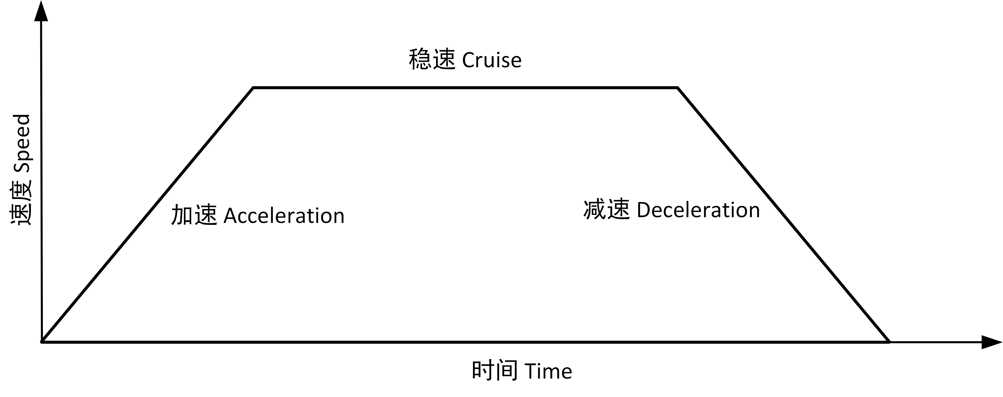
The movement speed curve of the robot is divided into three parts: acceleration, cruise and deceleration. The movement speed parameter determines the cruise, and the acceleration parameter determines the acceleration and the deceleration gradients, as shown in the figure.
Blend
When the robot is moving, if you have set the blend parameters, smooth transition between the two trajectories can be achieved, so that the robot can move faster and more stable. For example, in the following figure, the robot is expected to reach [Waypoint_2] from [Waypoint_0], but because there are other items between the two waypoints, the robot has to start from [Waypoint_0] and go through [Waypoint_1] to reach [Waypoint_2]. Since [Waypoint_1] only exists to bypass other items, the robot is expected to expend minimal energy and time at [Waypoint_1]. At this time, adding the blend parameters will enable the robot to smoothly transition from the first trajectory to the second trajectory, eliminating the need for deceleration and acceleration at the intermediate point. This reduces the time and energy required for the robot to turn, thereby enhancing the movement efficiency.
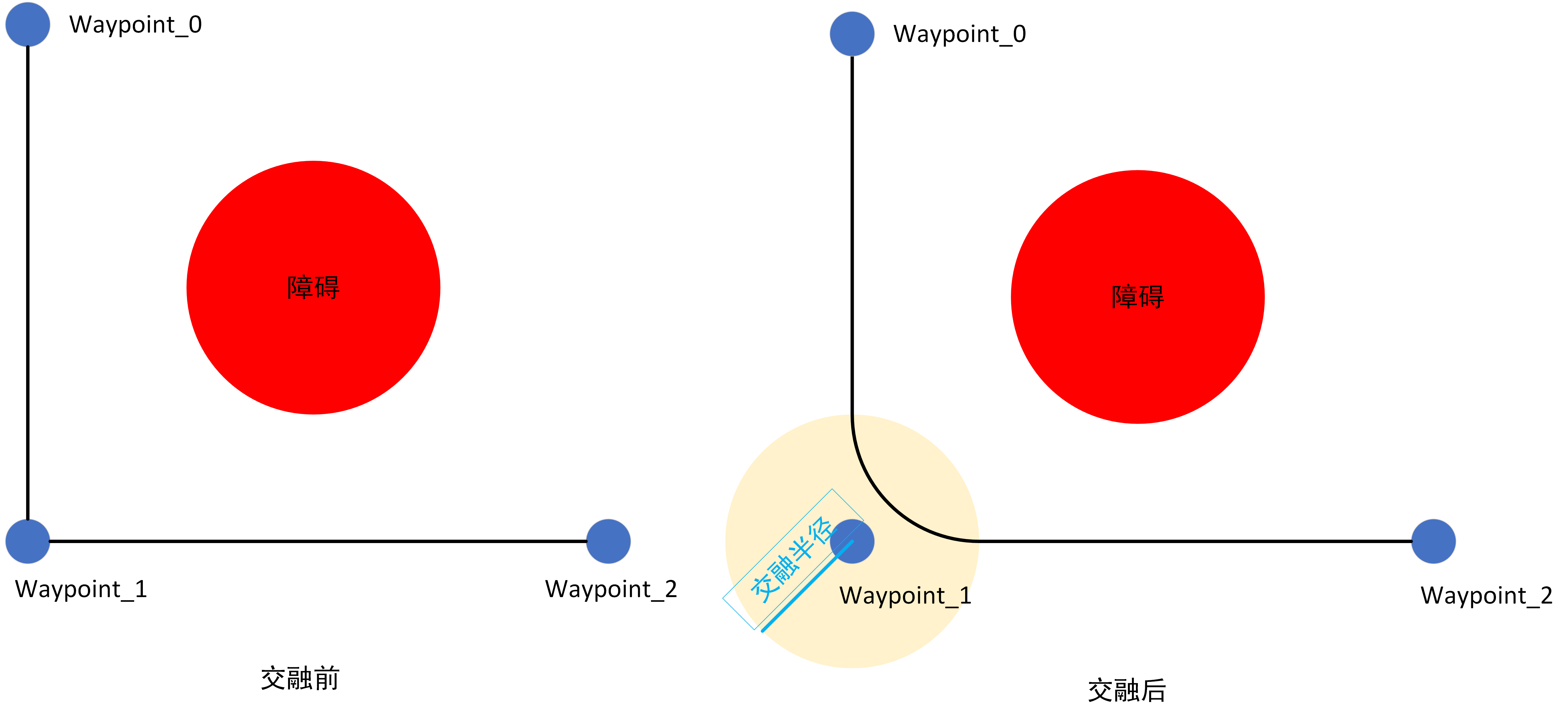
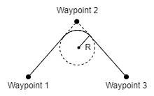
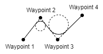
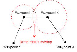
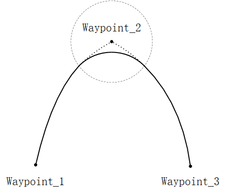
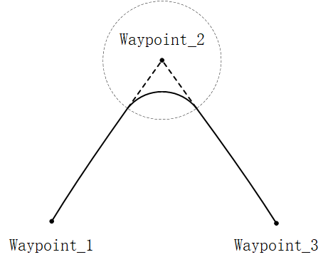
The main blend parameter is the blend radius, that is, the turning radius of the robot. When the robot is within the blend radius of a waypoint, blend feature may be activated, allowing the robot to deviate from its original path and move continuously without stop at the waypoint. The smaller the blend radius, the larger the path angle; and the larger the blend radius, the smaller the path angle. Note, however, that overlaps shall be avoided in blend, as shown in the figure below.
Other parameters that affect the blend trajectory:
- Movement type (MoveJ, MoveL, MoveS) at the StartPoint and EndPoint of blend.
- Robot movement time on the trajectory.
- Robot speed (joint speed/joint acceleration, tool speed/tool acceleration).
Blend trajectory
Blend in [MoveJ]: After the blend parameters are set, the system will generate a smooth curve in the joint space.
Blend in [MoveL]: After the blend parameters are set, an arc path will be planned at the blend position, following a direction blended with the smooth interpolation between the two trajectories.
Shared parameter
The Shared parameter feature enables bulk setting of parameters in this program block. For example, after setting of [Shared parameter] in [Move] node, all nodes added to the [Move] program block will, by default, apply the values set in the [Move] node for any parameters included in [Shared parameters], unless those parameters are specifically set.
Coordinate
As the robot moves, the software calculates the position of the TCP within the selected coordinate system, so the motion trajectory of the robot may vary with the coordinate system selected. Two coordinate systems for base and tool are predefined, and you can also select a custom coordinate system here. See "5.1.9 Coordinate system" for the description and settings of coordinate system.
Tool center point (TCP)
Select a different TCP to adjust the movement mode of the robot between waypoints. The TCP for [Waypoint] can be set in the [Move] node. See "5.1.4 TCP" for the description and settings of TCP.
- Use Active TCP.
- Ignore Active TCP, allowing adjustment of this movement in relation to the Tool Flange.
- Custom TCP.
Use joint angles
Once checked, the joint angles will be recorded in the scripts when the program is running, replacing the location information of the robot. And the system will disable the [Set TCP] and [Coordinate] here. If this feature is activated, the waypoint information will remain unchanged during project migration, allowing the robot to keep using the data without adjustment.
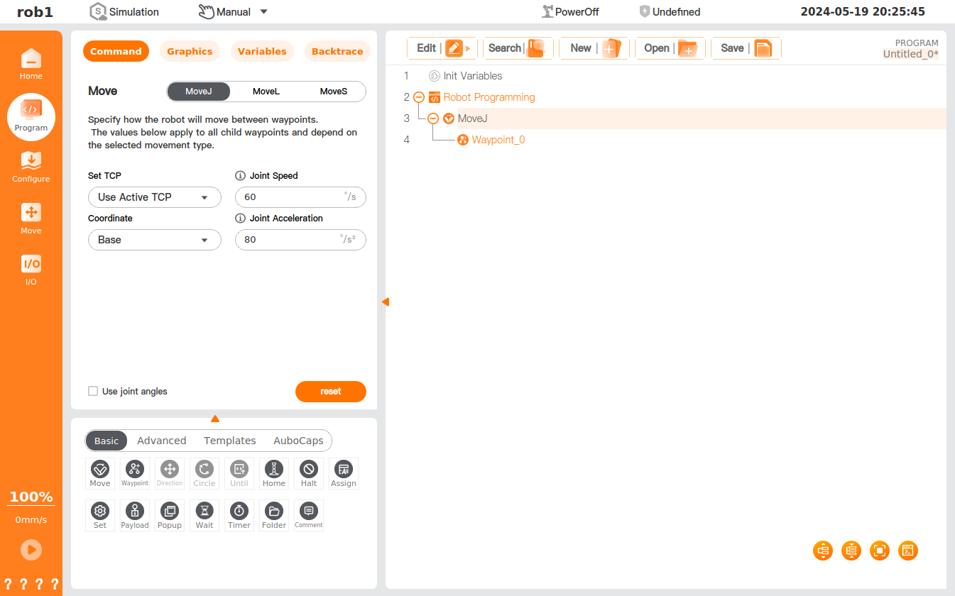
Add [Move] node
- Tap the [Move] icon to add a [MoveJ] node to the program tree, including a [Waypoint] node under it.
- The [Move] node contains movement types such as MoveJ, MoveL and MoveS. The display name of the [Move] node in the program tree is determined by the movement type you select.
- Select the [MoveJ/MoveL/MoveS] node to set the node.
Add [MoveS]
- Tap the [Move] command to add a [Move] node to the program tree.
- Select [MoveS] in the [Move] command interface.
- Set the relevant parameters of the MoveS: TCP, Coordinate, Joint Speed, Joint Acceleration, etc.
- Under the [MoveS] node, add several [Waypoint] nodes and configure the location for each waypoint to finalize the [MoveS] addition.