CAN Bus Error Software Troubleshooting Guide
Background
During robot arm operation, a CAN bus error pop-up may suddenly appear. Because hardware troubleshooting requires certain hardware knowledge and some additional tools, this guide explains the troubleshooting steps from the software and log perspectives.
Software Fix History
During the iterations of the upper-computer program, the software bugs found in actual use and testing have basically been resolved, including but not limited to:
- Data communication blocking
- Automatic checks for CAN and CAN FD
- Error reporting when transmitting overly large byte counts
Issue Categories
The causes of CAN bus error pop-ups are divided into several categories here:
- Misoperation issues
- Version incompatibility issues
- Hardware issues
1. Misoperation Issues
1. After upgrading the firmware package, a “CAN bus error” pop-up appears
The robot arm was originally running normally. To resolve other issues (such as false collision alarms or failure to reach full speed), the firmware was upgraded, and the error appeared after the upgrade. This is generally caused by an incompatible uploaded version upgrade package. It is recommended to directly roll back the firmware version to ensure the robot arm can run, and then communicate with R&D about whether to upgrade and which version to select.
2. Version Incompatibility Issues
Background
The bootloader of the robot arm joint main control chip was improved and upgraded from v1.0.x to v1.1.x, but this upgrade caused firmware version upgrades to be unable to go directly from v1.0.x to v1.1.x.
The affected joint models include: all i series joints, all C series joints, and all iH series joints.
The affected base models include: bases with the silkscreen ROBOT POWER Board V1.2 that use the base_i_C_h120-*.hex firmware.
[Detailed instructions document]
Solution
- Use J-Link to download the bootloader firmware package containing version
v1.1.x, and then perform a normal online upgrade. - Upgrade again to the
v1.0.xfirmware to return to versionv1.0.x.
Related Log Output
At this point, the firmware update fails, and the log outputs the following statement: 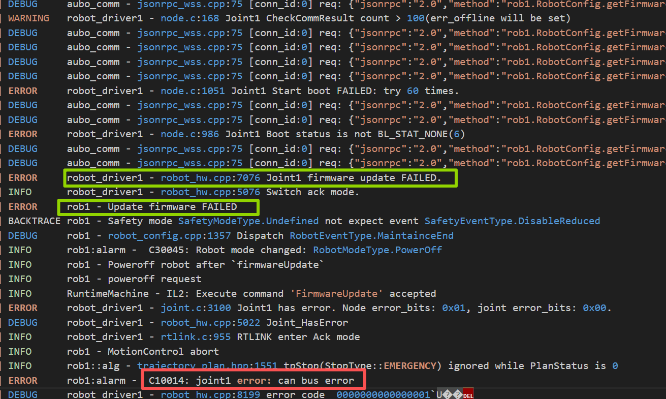
3. Hardware Issues
Several common hardware issues and how they appear in logs are listed below.
Phenomenon 1
During robot arm operation, a “CAN bus hardware error” is suddenly reported. First check whether the cables are properly connected. If they are connected properly, the issue is most likely with the CAN hard wiring (for example, loosening due to mechanical friction, or adhesive loosening due to high temperature), causing the CAN line to become unstable while the robot arm is moving.
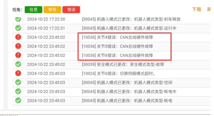

Phenomenon 2
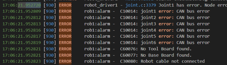
Here, all 6 joints report errors, and communication with the tool board, base board, and robot is disconnected. This is also a typical hardware issue.
Phenomenon 3
When the robot arm cable is too long, there is a probability that a “CAN bus error” will be reported, mainly because of signal delay and instability.
Phenomenon 4
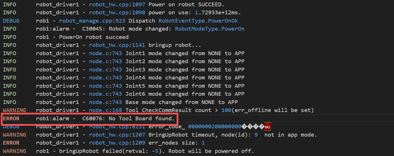
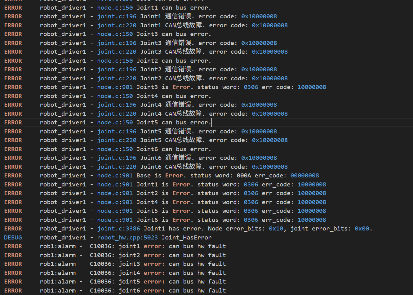
Here, you can see that an error indicating that the tool board cannot be found is reported during power-on. This can also cause a “CAN bus error” to be reported.
CAN Line Damage Image
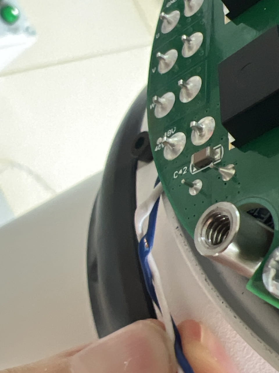
PS: Regarding the resolution of hardware issues, if conditions on site permit, you can follow the CAN Error Hardware Troubleshooting Manual to perform preliminary hardware troubleshooting. If conditions do not permit, arrange return-to-factory repair.
4. Log Error Code Classification and Analysis
/// Error codes
#define ERR_OVER_CURRENT_BIT    (((uint32_t)0x01) << 0) ///< Overcurrent
#define ERR_OVER_VOLTAGE_BIT    (((uint32_t)0x01) << 1) ///< Overvoltage
#define ERR_OVER_TEMPRATURE_BIT (((uint32_t)0x01) << 2) ///< Overtemperature
#define ERR_COMMUNICATION       (((uint32_t)0x01) << 3) ///< Communication
#define ERR_LOW_VOLTAGE           (((uint32_t)0x01) << 4) ///< Undervoltage
#define ERR_UVW_LOGIC_INVALID     (((uint32_t)0x01) << 5) ///< UVW logic invalid
#define ERR_UVW_ABZ_FAULT         (((uint32_t)0x01) << 6) ///< ABZ phase error
#define ERR_ABS_ENC_COMM_FAULT    (((uint32_t)0x01) << 7) ///< Absolute encoder error
#define ERR_ADC_ZERO_OFFSET_FAULT (((uint32_t)0x01) << 8) ///< ADC zero offset error
#define ERR_ENC_POLLUTE           (((uint32_t)0x01) << 9) ///< Encoder contamination level error
#define ERR_ENC_Z_LOST            (((uint32_t)0x01) << 10) ///< Z phase lost
#define ERR_ENC_CALI_FAULT        (((uint32_t)0x01) << 11) ///< Encoder calibration error
#define ERR_IMU_FAULT             (((uint32_t)0x01) << 12) ///< Inertial measurement unit fault
#define ERR_IPM_NTC_FAULT         (((uint32_t)0x01) << 13) ///< NTC fault
#define ERR_ABS_ENC_LOW_VOLT      (((uint32_t)0x01) << 14) ///< Absolute encoder low voltage
#define ERR_SHROT_CIRCUIT_FAULT   (((uint32_t)0x01) << 15) ///< Short-circuit fault
#define ERR_POS_OVER_LIMIT        (((uint32_t)0x01) << 16) ///< Position over limit
#define ERR_MOTOR_STALL           (((uint32_t)0x01) << 17) ///< Motor stall
#define ERR_ABS_MT_FAULT          (((uint32_t)0x01) << 18) ///< Absolute encoder multiturn fault
#define ERR_MOTOR_PHASE_LOSE      (((uint32_t)0x01) << 19) ///< Motor phase loss
#define ERR_BRAKE_FAULT           (((uint32_t)0x01) << 20) ///< Brake fault
#define ERR_REDUCER_OVER_TEMP     (((uint32_t)0x01) << 21) ///< Reducer overtemperature
#define ERR_REDUCER_NTC_FAULT     (((uint32_t)0x01) << 22) ///< Reducer NTC fault
#define ERR_FIRMWARE_UPDATE_FAULT (((uint32_t)0x01) << 23) ///< Firmware update error
#define ERR_FLASH_OP_FAIL         (((uint32_t)0x01) << 24) ///< FLASH operation fault
#define ERR_EXT_ABS_ENC_COMMFAULT \
    (((uint32_t)0x01) << 25) ///< Reducer-end encoder communication fault
#define ERR_BATTERY_LOW      (((uint32_t)0x01) << 26) ///< Battery low power
#define ERR_PHASE_ALIGN_FAIL (((uint32_t)0x01) << 27) ///< Lock magnet pole
#define ERR_CAN_BUS          (((uint32_t)0x01) << 28) ///< CAN hardware error
#define ERR_POS_CMD          (((uint32_t)0x01) << 29) ///< Position command discontinuity
#define ERR_POS_INIT         (((uint32_t)0x01) << 30) ///< Position initialization failed
#define ERR_TORQUE_SENSOR    (((uint32_t)0x01) << 31) ///< Torque sensor fault
Error Code Usage Example
The log reports the following error:

The log outputs the error code 0x10000008. This is hexadecimal. Convert it to binary and then compare it against the error code table.
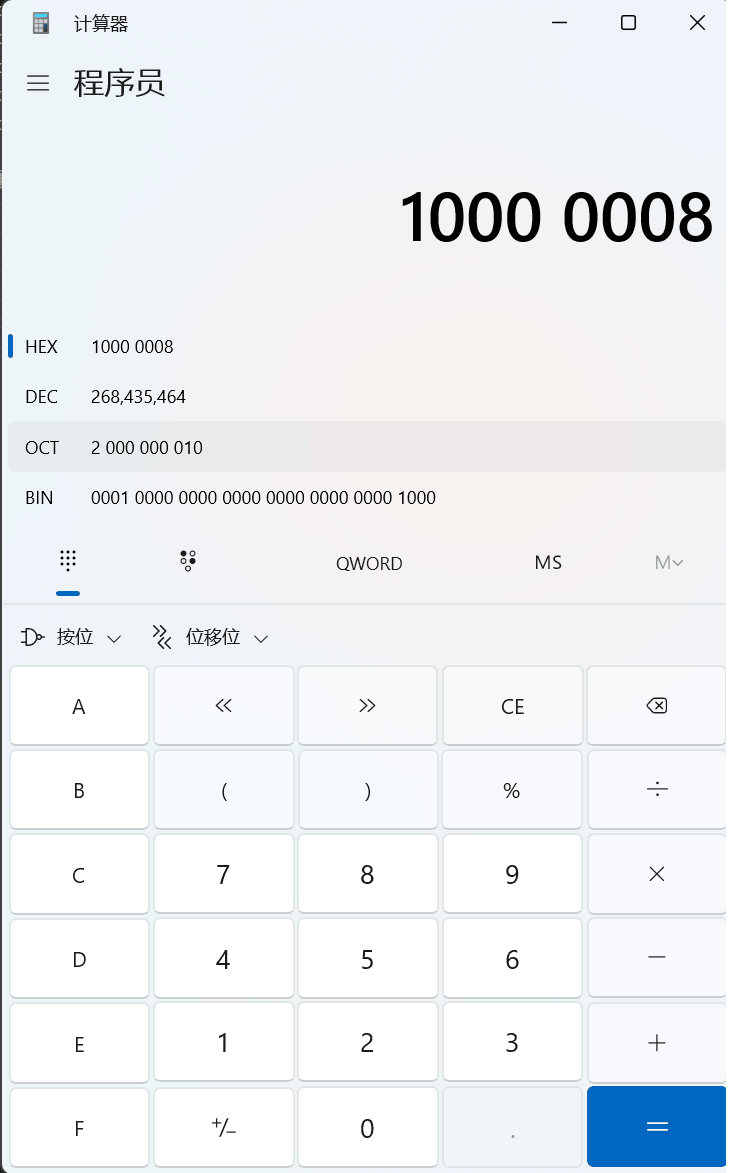
You can see that in binary, the values of bit 3 and bit 28 are 1 (starting from 0), which means:
- Communication issue
- CAN hardware error
If conditions permit, disassemble the robot arm and check whether the corresponding hardware has issues. Otherwise, it is recommended to return it to the factory for repair.