ARCS Software and Firmware Version Upgrade Guide
1 Overview
ARCS teach software includes two versions: the wired version (AuboStudio) and the wireless client (AuboStudio APP). The wired teach software (AuboStudio) is installed directly in the controller and can be used through a wired teach pendant. The wireless client teach software (AuboStudio APP) is installed on a wireless teach pendant (such as a tablet), and users send commands to the controller through the wireless teach pendant.
Both ARCS teach software and firmware can be upgraded online or offline. Select the appropriate upgrade method based on your actual environment.
Online upgrade: For network configuration, see ARCS Software Network Configuration Instructions.
Offline upgrade: You must first download the corresponding files, such as the
.apkclient installation package,.runsoftware installation package,.firmfirmware upgrade package, etc. Then import the downloaded files into the controller through the teach software, a USB flash drive, or other methods, and then perform the upgrade.
1.1 Installation Package Download Links
.apkclient installation package: https://download.aubo-robotics.cn/android/.runsoftware installation packagearm version: https://download.aubo-robotics.cn/arcs/arm64/

x86 version: https://download.aubo-robotics.cn/arcs/

.firmfirmware package: https://download.aubo-robotics.cn/firmware/
注意
- Wired-end upgrade: Download the
.runsoftware installation package. For the correspondence between software versions and controller models, see “Appendix 1: ARCS Software Version and Controller Model Correspondence Table”. - Wireless-end upgrade: Download the
.apkclient installation package and the.runsoftware installation package. For the correspondence between software versions and client versions, see “Appendix 2: ARCS Software Version and App Version Correspondence Table”. - Firmware upgrade: Download the
.firmfirmware package. For joint chip models, joint interface connection locations, and interface board flashing locations, see “Appendix 3: Firmware Correspondence Table”, “Appendix 4: Robot Arm Joint Interface Connection Locations”, and “Appendix 5: Controller Interface Board Flashing Locations”, respectively.
1.2 Notes
- After installing the
.apkclient installation package and the.runsoftware installation package, you must restart the software for the new version to take effect. If the new version does not take effect after restarting the software, try switching versions manually. - After installing the
.firmfirmware upgrade package, you must power off the entire controller (disconnect the 220 V power supply) and restart it. - After each ARCS system upgrade is completed on the web version of AuboStudio, clear the cache to prevent page operation failures caused by cache conflicts. The wired and wireless teach pendant APP versions are not affected by this issue and require no additional operation.
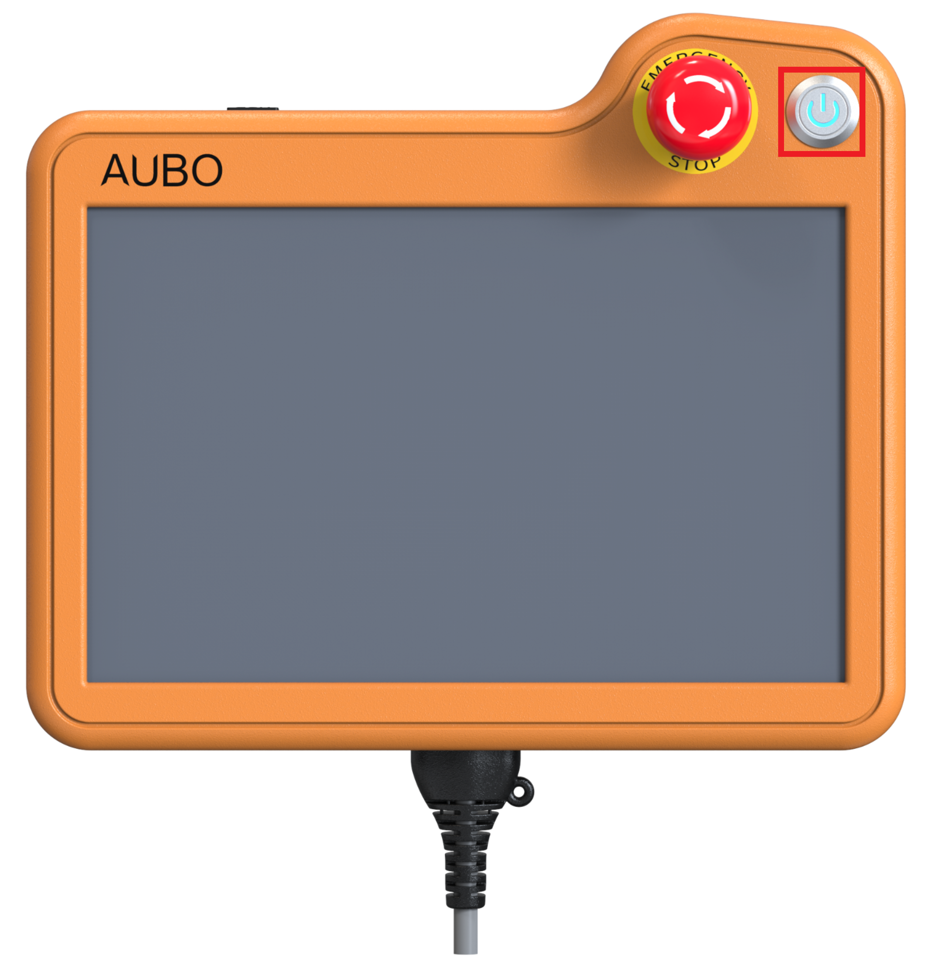
Note: The power button on the teach pendant cannot restart the firmware. You must power off the entire controller and restart it.
2 Software Upgrade
For the ARCS software versions supported by different controller models, see “Appendix 1: ARCS Software Version and Controller Model Correspondence Table”. For the App versions supported by different ARCS versions, see “Appendix 2: ARCS Software Version and App Version Correspondence Table”.
2.1 Online Upgrade (Wired End)
Ensure that the system can connect to the external network.
- For network configuration, see ARCS Software Network Configuration Instructions.
Open AuboStudio and click “Home > Settings > System > Software Upgrade” to enter the [Software Upgrade] screen. The software installation package list displays all currently upgradeable software versions. If the latest installation package is not found, try clicking the [Refresh] button to refresh the list.
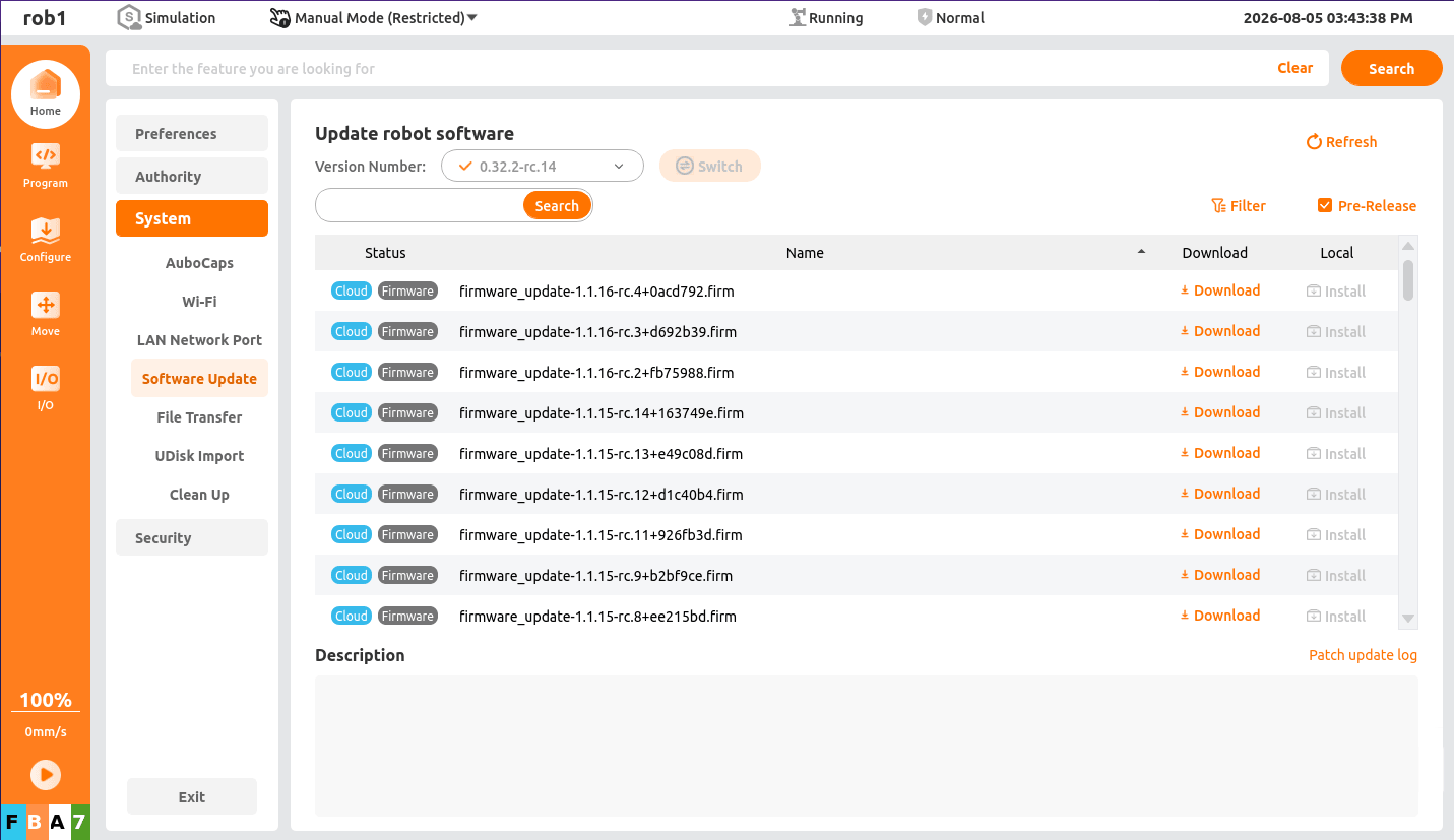
Click the [Download] button after the target software installation package to enter the [Download] screen and download the installation package.
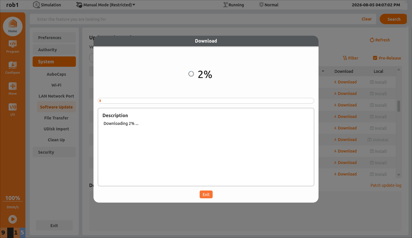
After the installation package is downloaded, an installation prompt box appears. Click [Install] to start the installation.
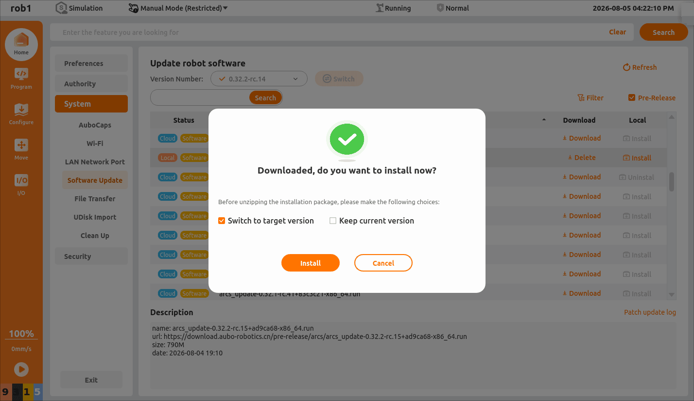
After the installation is complete, a [Shutdown] or [Restart] prompt box appears. Click [OK].
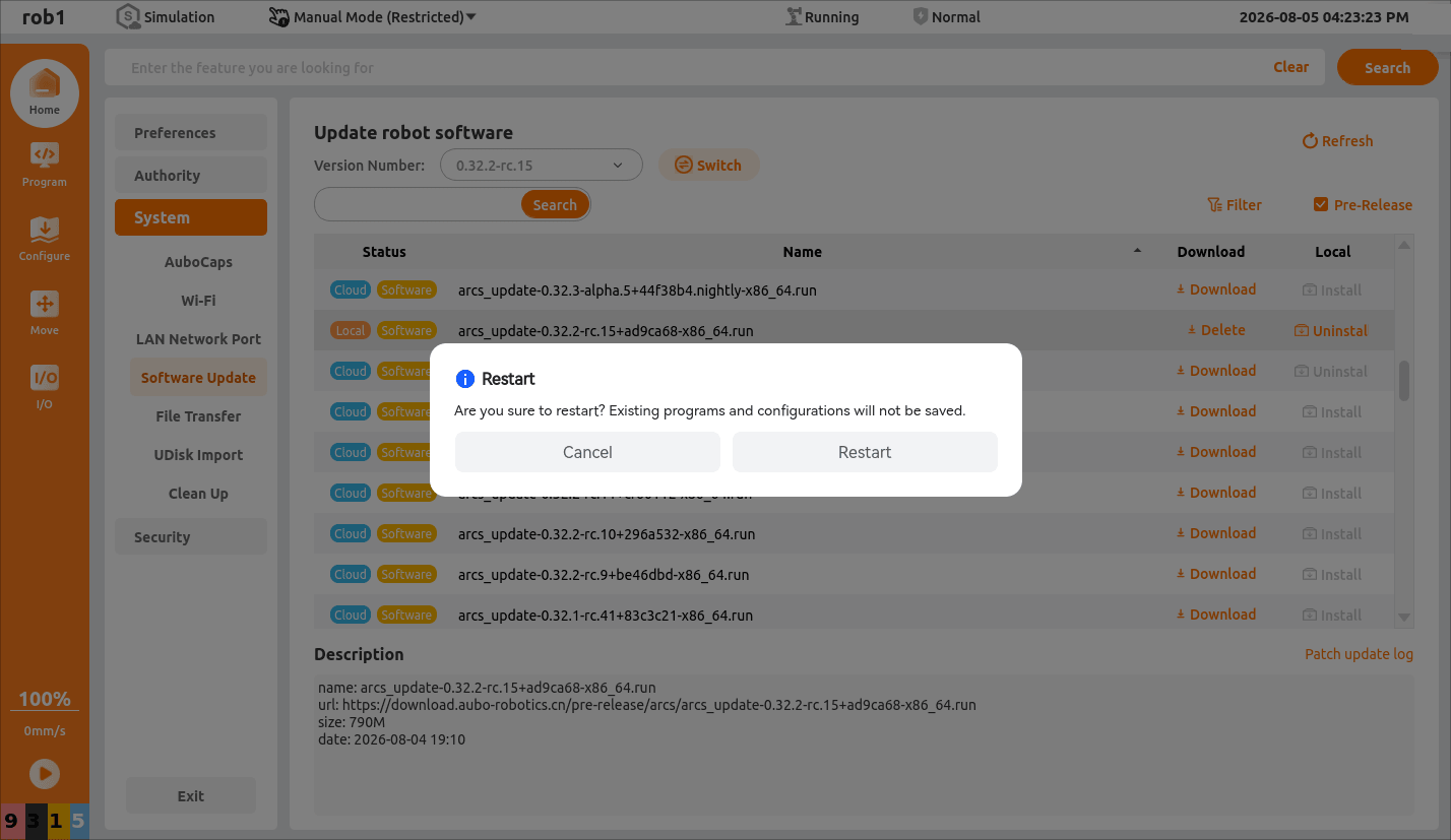
Press the power button on the teach pendant to power on again.
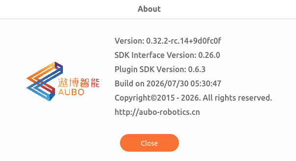
After startup, click “Home > About” to open the [About] prompt box and check whether the software version has been updated.
2.2 Offline Upgrade (Wired End)
For offline upgrade on the wired end, you must download the installation package in advance, import it into the controller through a USB flash drive or SSH remote login to the controller, and finally complete the software upgrade on the [Software Upgrade] screen of the teach software.
2.2.1 USB Flash Drive Import
Prerequisite: USB flash drive.
Procedure:
Download the
.runsoftware installation package in advance and copy the.runsoftware installation package to the root directory of the USB flash drive.- For the installation package download link, see “1.1 Installation Package Download Links” in this document.
Open AuboStudio and connect the teach software.
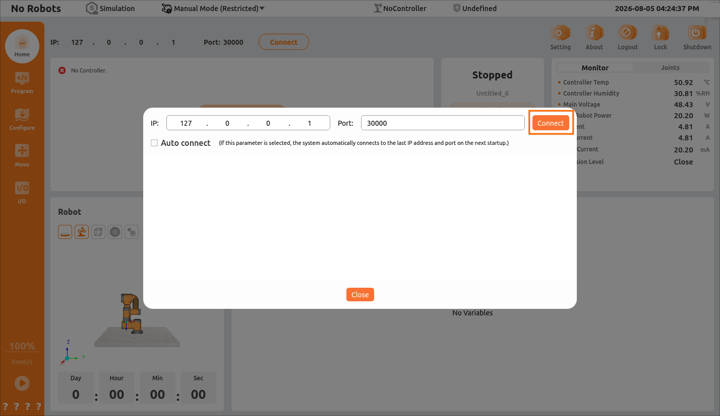
Insert the USB flash drive into the controller. On the main software screen, click “Settings > System > USB Drive Import” to enter the [USB Drive Import] screen and view the inserted USB flash drive and its files.
Click [Import] after the target installation package to import the installation package into the controller.
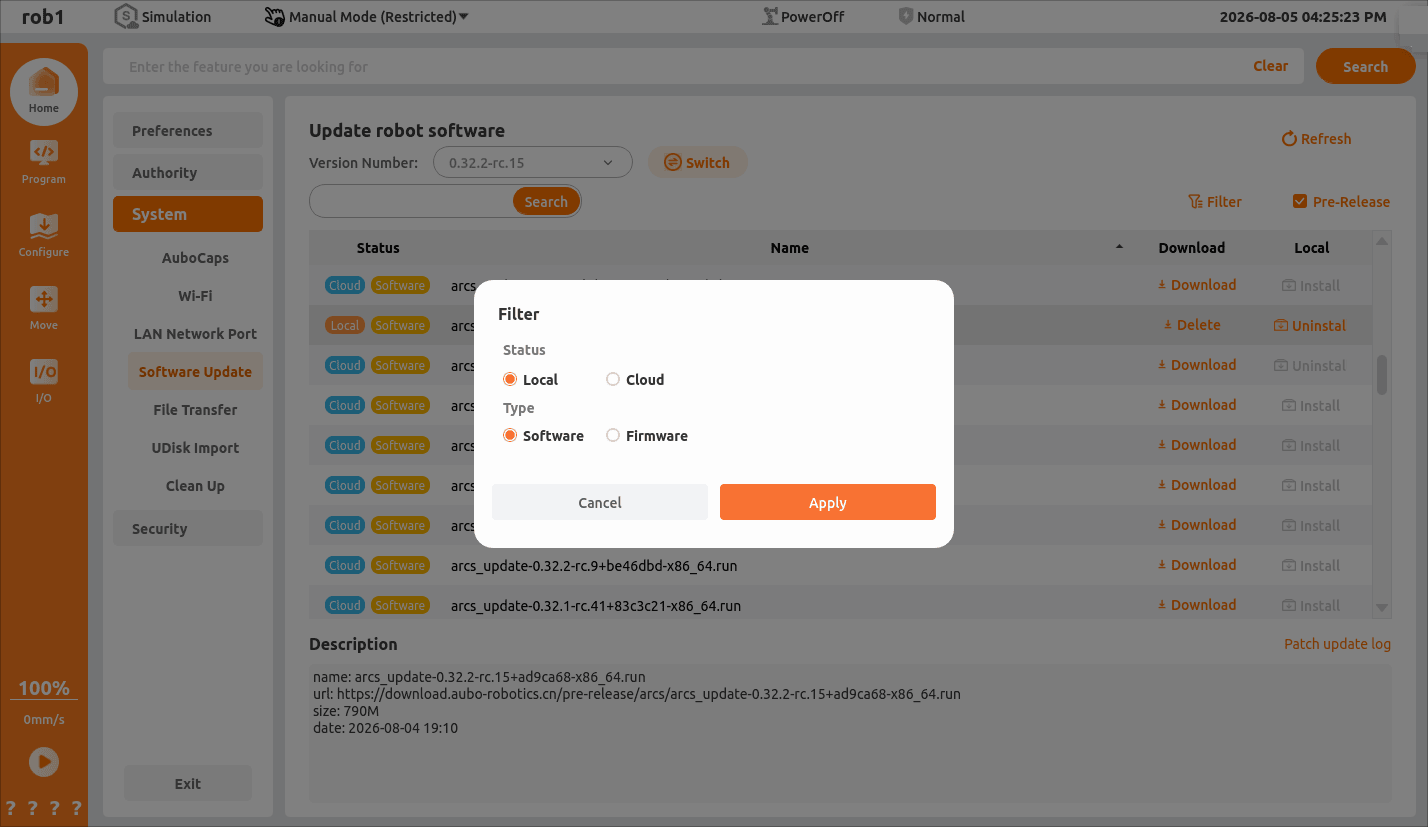
Click “Settings > System > Software Upgrade” to enter the [Software Upgrade] screen, and click [Filter] to open a dialog box.
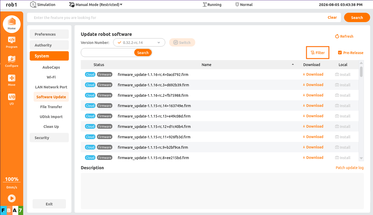
In the [Filter] dialog box, select [Local] for the [Status] filter condition, select [Software] for the [Type] filter condition, and click [Apply] to return.
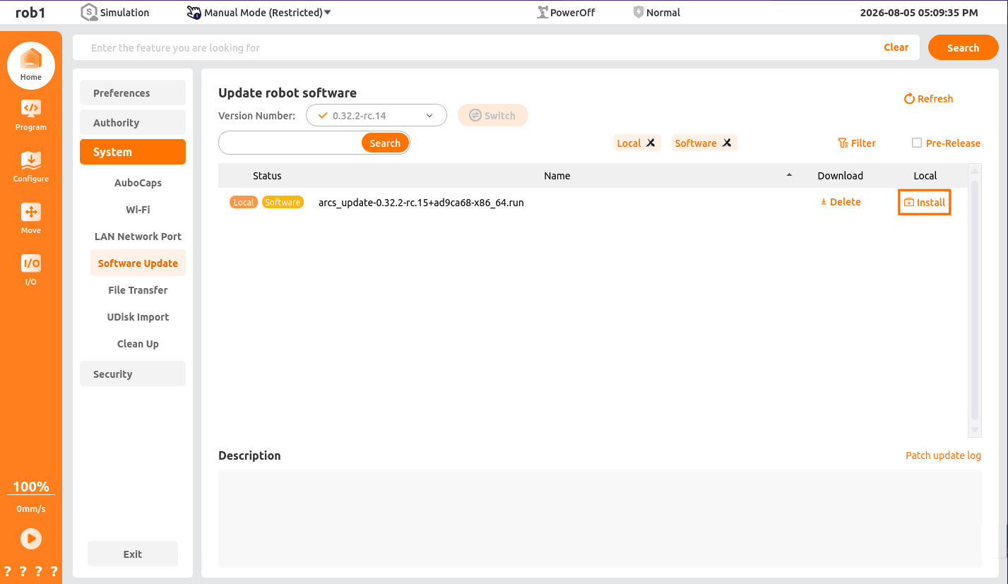
Find the installation package that was just imported in the installation package list and click [Install] to start the upgrade.
Wait until the screen indicates that the installation is complete. When the [Shutdown] or [Restart] prompt box appears, click [OK] to restart the software.
After powering on again, click “Home > About” to open the [About] prompt box and check whether the software version has been updated.
Note: Do not download the
.runsoftware installation package directly to the USB flash drive for use; otherwise, the system may not detect the installation package.
2.2.2 Copy Through SSH Remote Login
Prerequisites:
- A computer that can connect to the robot LAN.
- MobaXterm is installed on the computer.
Procedure:
Download the
.runsoftware installation package in advance.- For the download link, see “1.1 Installation Package Download Links” in this document.
Open AuboStudio and connect the teach software.
Open MobaXterm and connect to the robot. For the procedure, see: Using MobaXterm to Remotely Manage a Target Device.
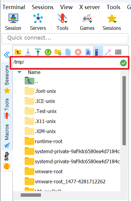
Go to the path: /tmp/.
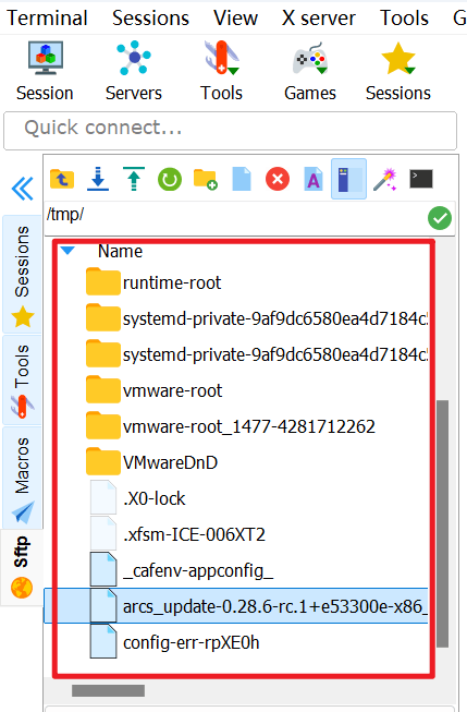
Drag the installation package to the left pane. After the copy succeeds, the installation package can be seen in the left pane.
Click “Settings > System > Software Upgrade” to enter the [Software Upgrade] screen, and click [Filter] to open a dialog box.
In the [Filter] dialog box, select [Local] for the [Status] filter condition, select [Software] for the [Type] filter condition, and click [Apply] to return.
Find the upgrade package that was just imported in the upgrade package list and click [Install] to start the upgrade.
Wait until the screen indicates that the installation is complete. When the [Shutdown] or [Restart] prompt box appears, click [OK] to restart the software.
After powering on again, click “Home > About” to open the [About] prompt box and check whether the software version has been updated.
2.3 Online Upgrade (Wireless End)
Ensure that the system can connect to the external network.
- For network configuration, see ARCS Software Network Configuration Instructions.
Open AuboStudio APP and click “Home > Settings > System > Update” to enter the [Update] screen. The software installation package list displays all currently upgradeable software versions and client versions. If the latest installation package is not found, try clicking the [Refresh] button to refresh the list.
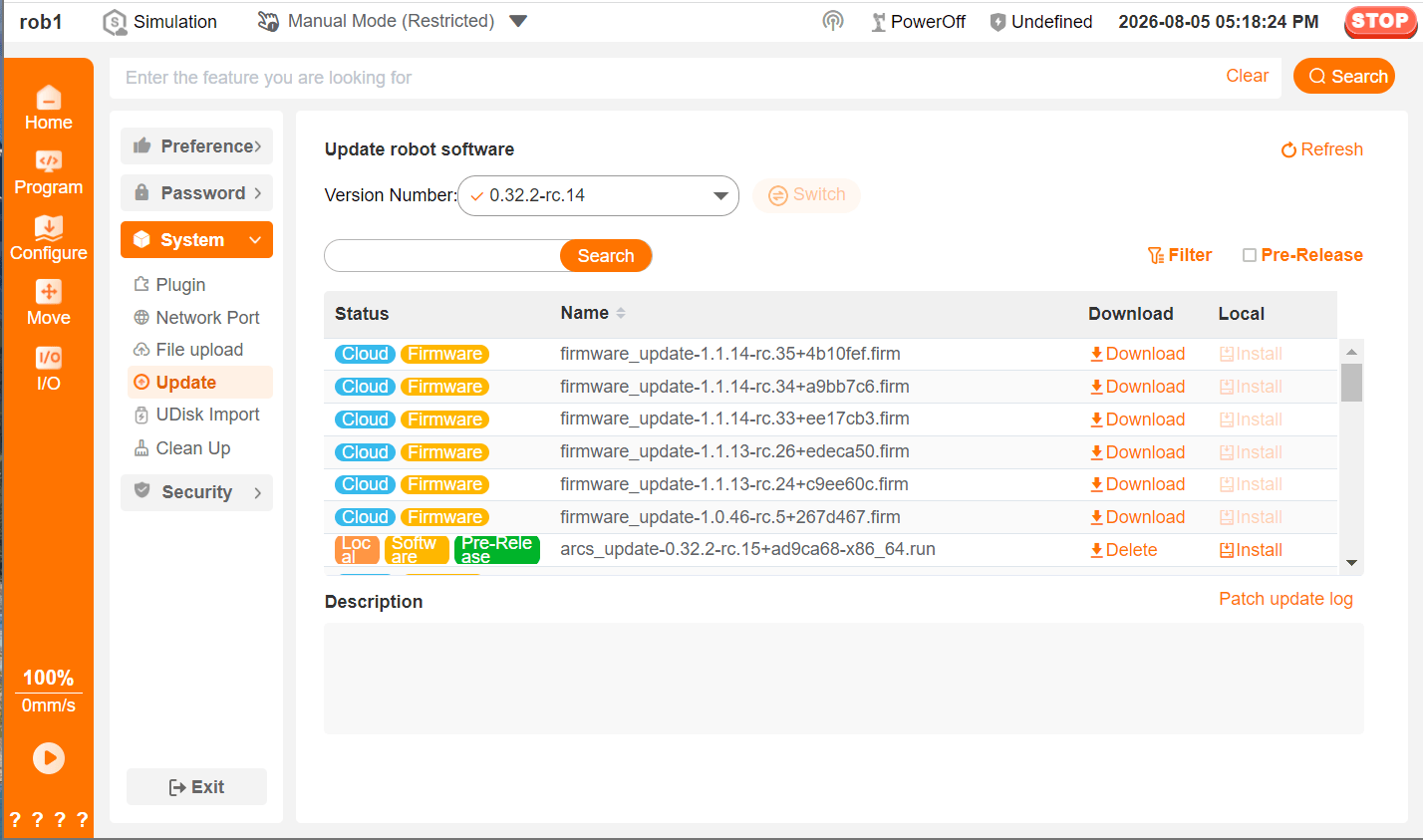
Click the [Download] button after the target
.runsoftware installation package. After entering the [Download] screen, download the installation package. After completion, click the [Exit] button to return to the [Update] screen.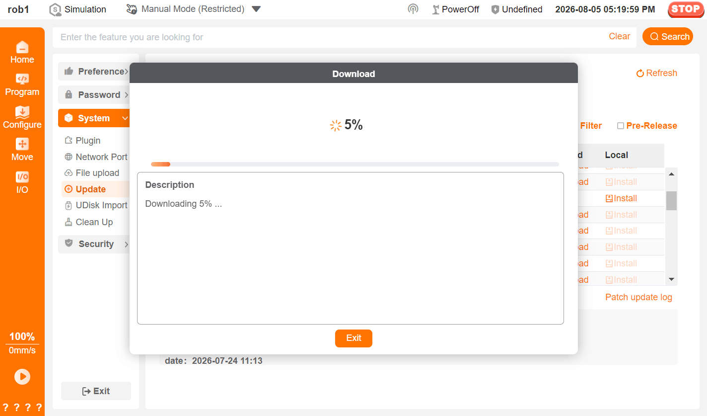
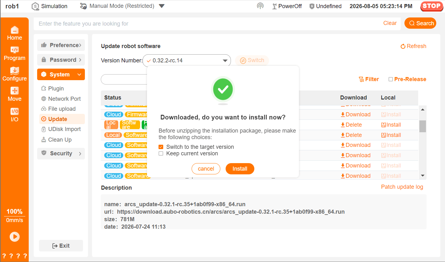
After the installation package is downloaded, an installation prompt box appears. Click the [Install] button to start the installation.
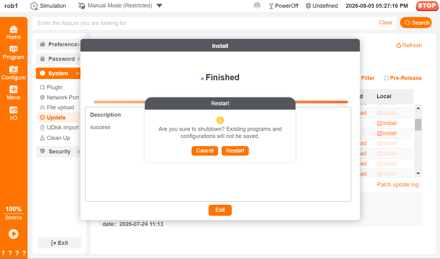
After the installation is complete, a [Shutdown] or [Restart] prompt box appears. Click [OK], and the wireless teach pendant disconnects from the controller.
Restart the client software (AuboStudio APP). After the controller finishes restarting, connect to the robot again.

Update the client software (AuboStudio APP):
Remark: If you do not need to update the client, skip this step.
Click “Home > Settings > System > Update” to enter the [Update] screen. Click the [Download] button after the target
.apkclient installation package. The system prompts you to download the file. Follow the system prompts to complete downloading and installing the client installation package.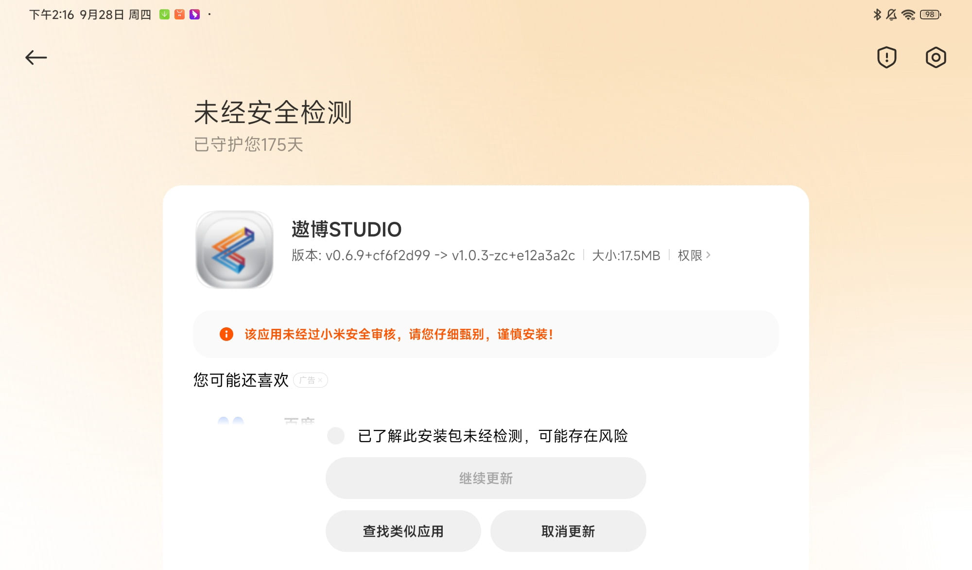
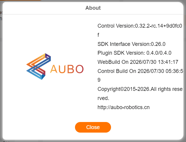
Start AuboStudio APP again and click “Home > About” to open the [About] prompt box and check whether the software version has been updated.
Confirm the following version information: - The App version corresponds to the client installation package version (
.apkfile)- The controller version corresponds to the software installation package version (
.runfile)
- The controller version corresponds to the software installation package version (
2.4 Offline Upgrade (Wireless End)
For offline upgrade on the wireless end, you must download the installation package in advance, import it into the controller through a USB flash drive, SSH remote login to the controller, or the client “File Upload” function, and finally complete the software upgrade on the [Update] screen of the teach software.
2.4.1 Client “File Upload”
Download the
.runsoftware installation package or.apkclient installation package in advance and transfer the installation package to the wireless teach pendant.- For the installation package download link, see “1.1 Installation Package Download Links” in this document.
Open AuboStudio APP, click “Home > Settings > System > File Upload”, and select the
.runsoftware installation package to upload it to the robot controller.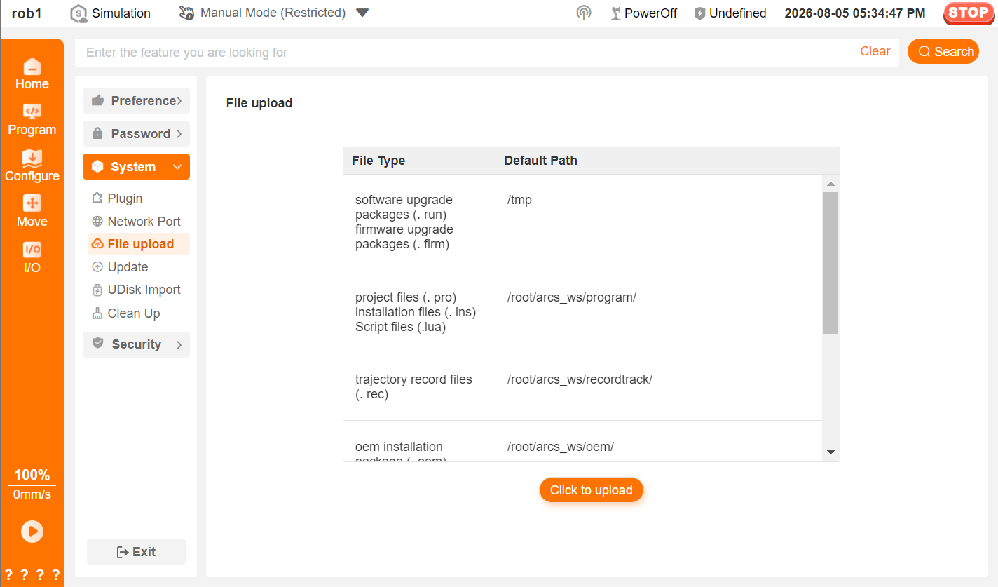
Click “Home > Settings > System > Update” to enter the [Update] screen, and click [Filter] to open a dialog box.
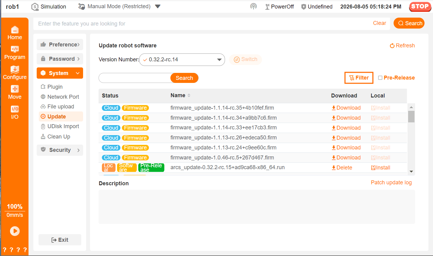
In the [Filter] dialog box, select [Local] for the [Status] filter condition, select [Software] for the [Type] filter condition, and click [OK] to return.
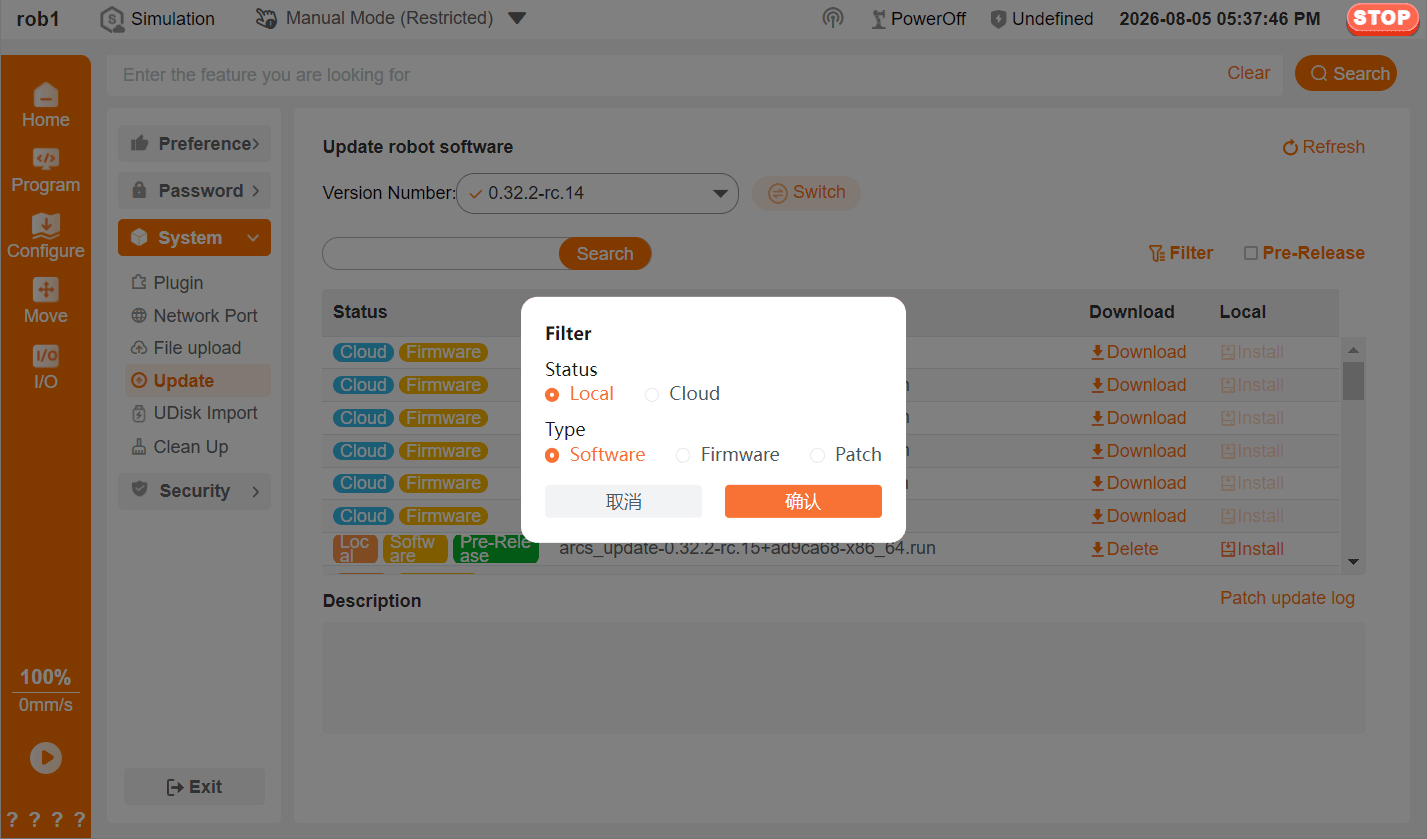
Find the installation package that was just imported in the installation package list and click [Install] to start the installation.
Wait until the screen indicates that the installation is complete. When the [Shutdown] or [Restart] prompt box appears, click [OK], and the wireless teach pendant disconnects from the controller.
Restart the client software (AuboStudio APP). After the controller finishes restarting, connect to the robot again.
Update the client software (AuboStudio APP):
Remark: If you do not need to update the client, skip this step.
Exit AuboStudio APP, click the local
.apkclient installation package, and follow the system prompts to complete client installation.Start AuboStudio APP again and click “Home > About” to open the [About] prompt box and check whether the software version has been updated.
Confirm the following version information: - The App version corresponds to the client installation package version (
.apkfile)- The controller version corresponds to the software installation package version (
.runfile)
- The controller version corresponds to the software installation package version (
2.4.2 USB Flash Drive Import
Prerequisite: USB flash drive.
Procedure:
Download the
.runsoftware installation package or.apkclient installation package in advance and copy the.runsoftware installation package to the root directory of the USB flash drive.- For the installation package download link, see “1.1 Installation Package Download Links” in this document.
Open AuboStudio APP and connect to the controller.
Insert the USB flash drive into the controller. On the main software screen, click “Settings > System > USB Drive Import” to enter the [USB Drive Import] screen and view the inserted USB flash drive and its files.
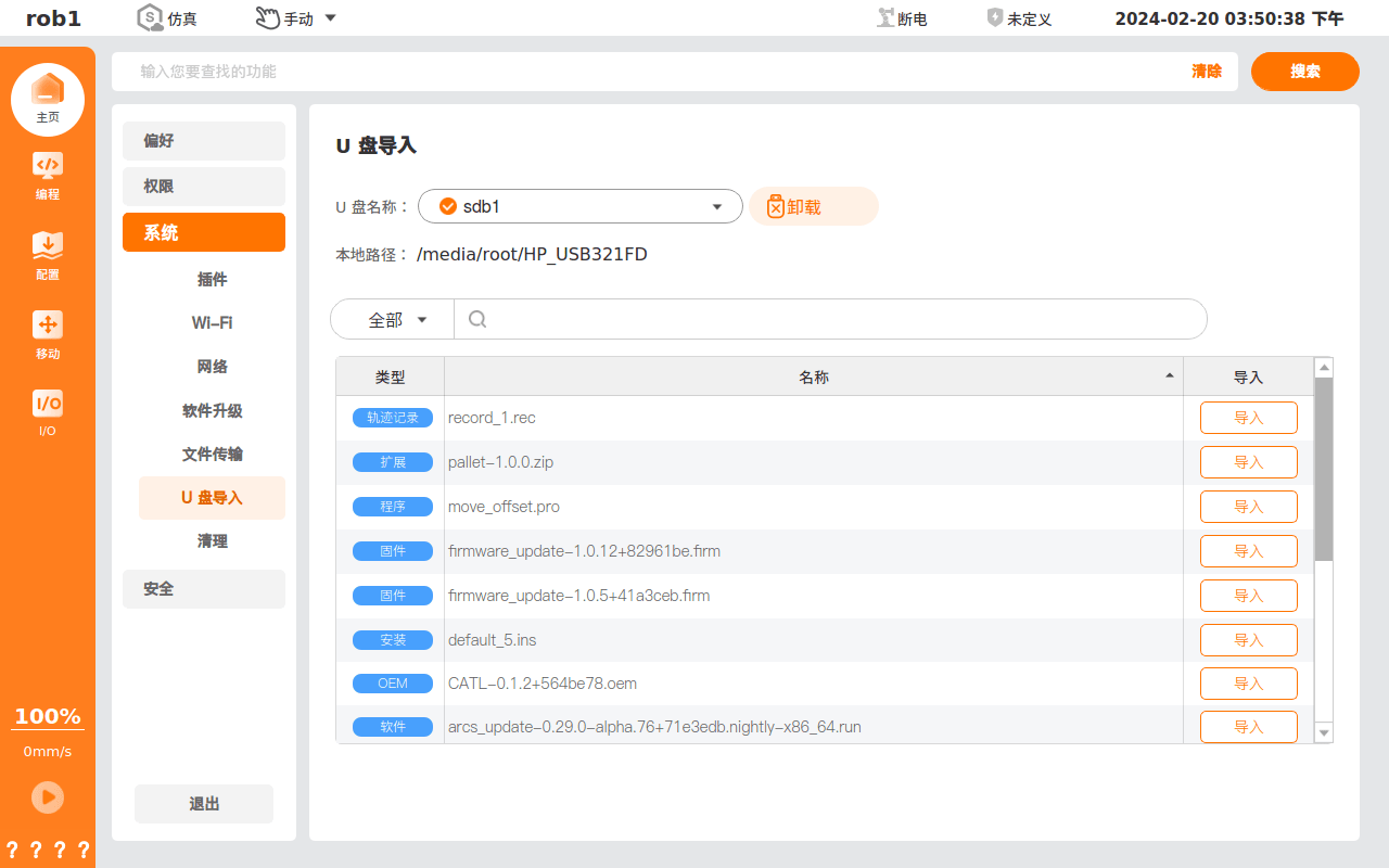
Click [Import] after the target installation package to import the installation package into the controller.
Click “Home > Settings > System > Update” to enter the [Update] screen, and click [Filter] to open a dialog box.
In the [Filter] dialog box, select [Local] for the [Status] filter condition, select [Software] for the [Type] filter condition, and click [Apply] to return.
Find the installation package that was just imported in the installation package list and click [Install] to start the installation.
Wait until the screen indicates that the installation is complete. When the [Shutdown] or [Restart] prompt box appears, click [OK], and the wireless teach pendant disconnects from the controller.
Restart the client software (AuboStudio APP). After the controller finishes restarting, connect to the robot again.
Update the client software (AuboStudio APP):
Remark: If you do not need to update the client, skip this step.
Exit AuboStudio APP, click the local
.apkclient installation package, and follow the system prompts to complete client installation.Start AuboStudio APP again and click “Home > About” to open the [About] prompt box and check whether the software version has been updated.
Confirm the following version information: - The App version corresponds to the client installation package version (
.apkfile)- The controller version corresponds to the software installation package version (
.runfile)
- The controller version corresponds to the software installation package version (
Note: Do not download the
.runsoftware installation package directly to the USB flash drive for use; otherwise, the system may not detect the installation package.
2.4.3 Copy Through SSH Remote Login
Prerequisites:
- A computer that can connect to the robot LAN.
- MobaXterm is installed on the computer.
Procedure:
Download the
.runsoftware installation package or.apkclient installation package in advance.- For the download link, see “1.1 Installation Package Download Links” in this document.
Open AuboStudio APP and connect to the controller.
Open MobaXterm and connect to the robot. For the procedure, see: Using MobaXterm to Remotely Manage a Target Device.
Go to the path: /tmp/.
Drag the installation package to the left pane. After the copy succeeds, the installation package can be seen in the left pane.
Click “Home > Settings > System > Update” to enter the [Update] screen, and click [Filter] to open a dialog box.
In the [Filter] dialog box, select [Local] for the [Status] filter condition, select [Software] for the [Type] filter condition, and click [Apply] to return.
Find the installation package that was just imported in the installation package list and click [Install] to start the installation.
Wait until the screen indicates that the installation is complete. When the [Shutdown] or [Restart] prompt box appears, click [OK], and the wireless teach pendant disconnects from the controller.
Restart the client software (AuboStudio APP). After the controller finishes restarting, connect to the robot again.
Update the client software (AuboStudio APP):
Remark: If you do not need to update the client, skip this step.
Exit AuboStudio APP, click the local
.apkclient installation package, and follow the system prompts to complete client installation.Start AuboStudio APP again and click “Home > About” to open the [About] prompt box and check whether the software version has been updated.
Confirm the following version information: - The App version corresponds to the client installation package version (
.apkfile)- The controller version corresponds to the software installation package version (
.runfile)
- The controller version corresponds to the software installation package version (
3 Firmware Upgrade
3.1 Online Upgrade
Firmware online upgrade means upgrading firmware through the ARCS teach software.
The method for upgrading firmware through the ARCS teach software is similar to the method for upgrading software:
Method 1: After the controller is connected to the external network, download the firmware package directly on the [Software Upgrade/Update] screen of the ARCS teach software, and complete the firmware upgrade according to the prompts on the software screen.
Method 2: Download the firmware package in advance, import it into the controller through a USB flash drive, SSH remote login to the controller, or the client “File Upload” function, and finally complete the firmware upgrade on the [Software Upgrade/Update] screen of the teach software.
3.2 Offline Upgrade
Firmware offline upgrade means connecting the robot joints and computer through other hardware, and directly flashing the code to the interface board.
3.2.1 J-Link
Preparations
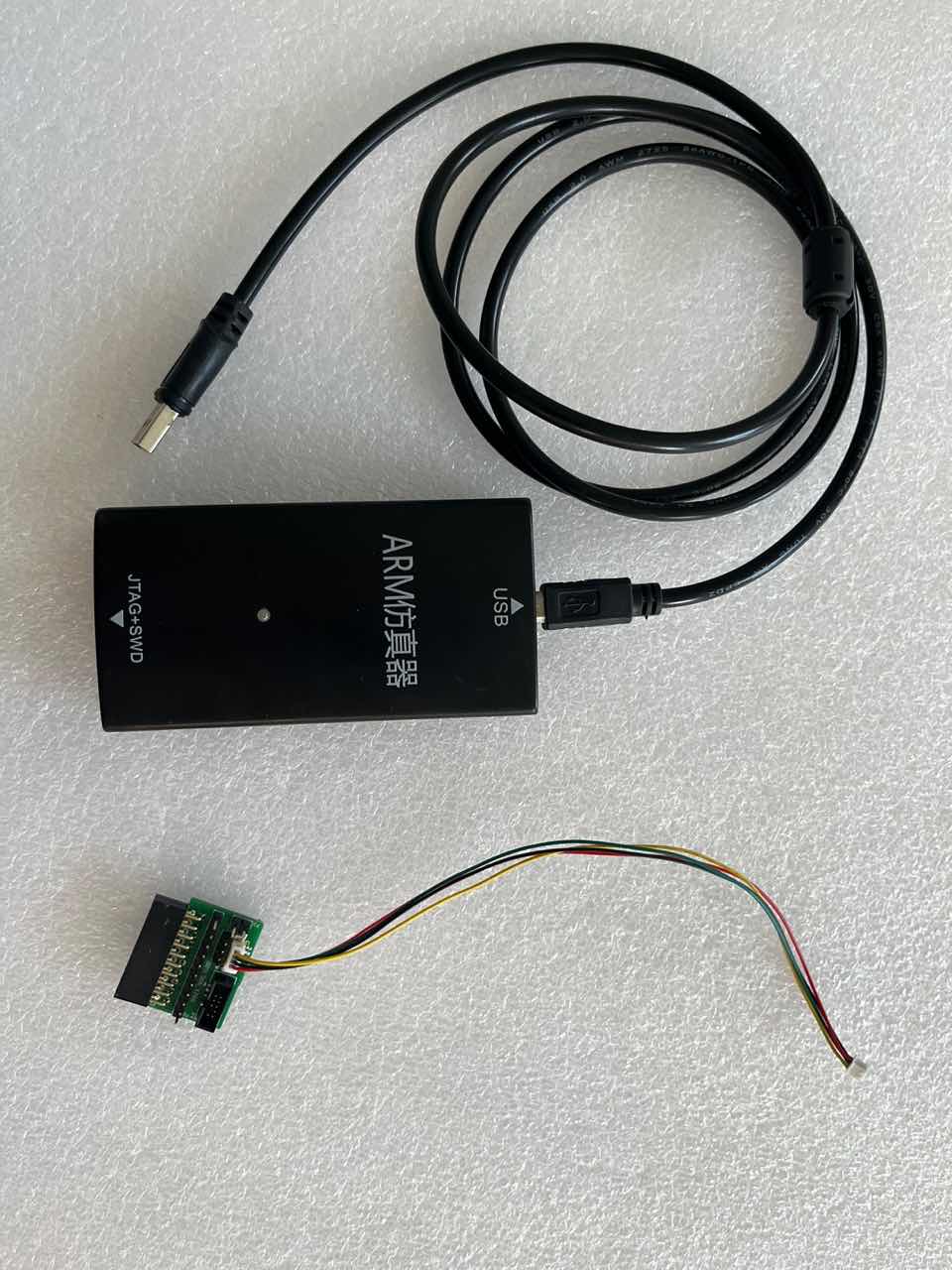
J-Link connection cable:
J-Flash software installation:
Download links:
- Official website link: https://www.segger.com/downloads/jlink/
- Cloud disk link: download.aubo-robotics.cn/tools/JLink_Windows_V752d_x86_64.exe
After downloading the installation package, select the default options to install it.
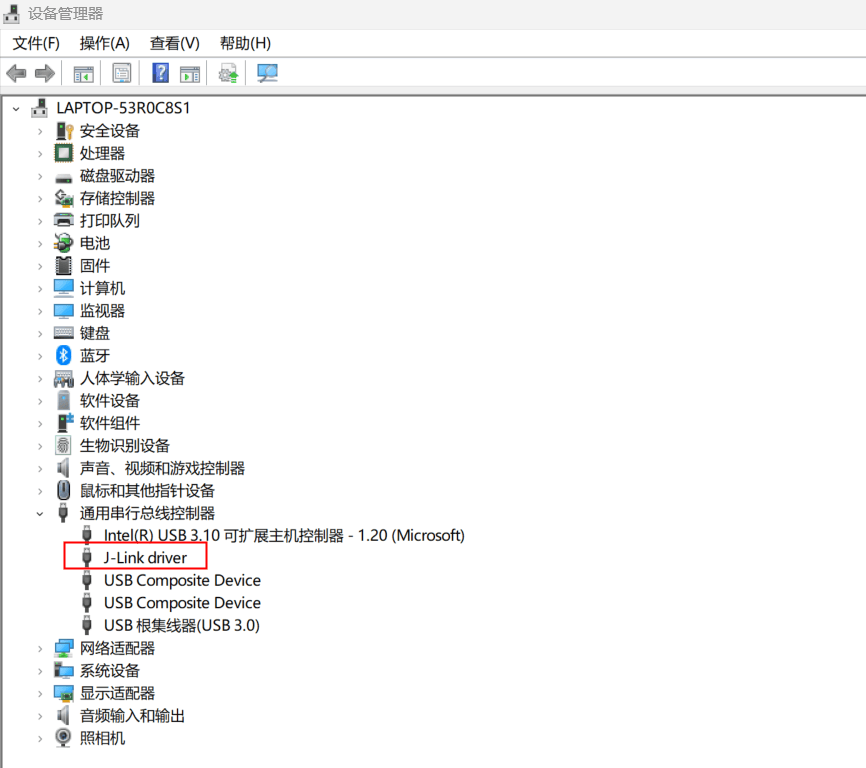
After installation is complete, connect the J-Link connection cable and enter [Device Manager] to check whether the driver was installed successfully.
.hexfile:.hexfiles differ for different chip types. For the correspondence, see “Appendix 3: Firmware Correspondence Table”.Add internal and external firmware flashing algorithm files:
Algorithm files: Change the
.firmfile suffix to.zip, decompress the firmware package (on Linux, the.firmfile can be opened directly), and open the pathfirmware_update-xxx\offline_flash\jflashin the firmware package.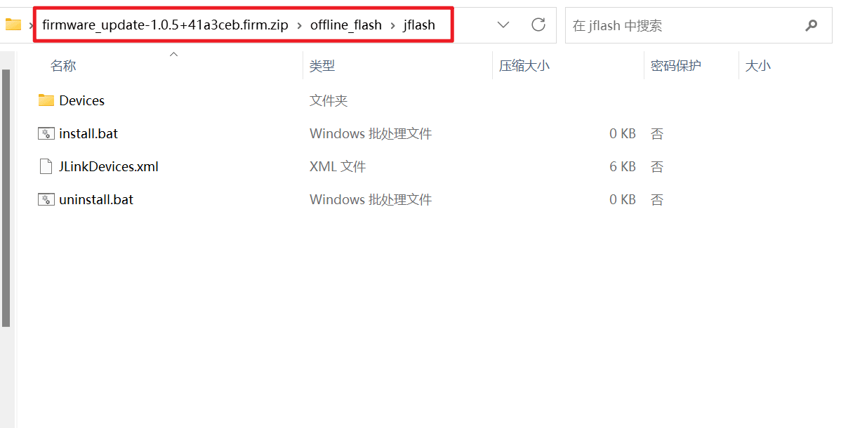
Copy
DevicesandJLinkDevices.xmlunderfirmware_update-xxx\offline_flash\jflashtoC:\Program Files\SEGGER\JLink. (The above is the default path. If it has been changed, use the corresponding modified path.)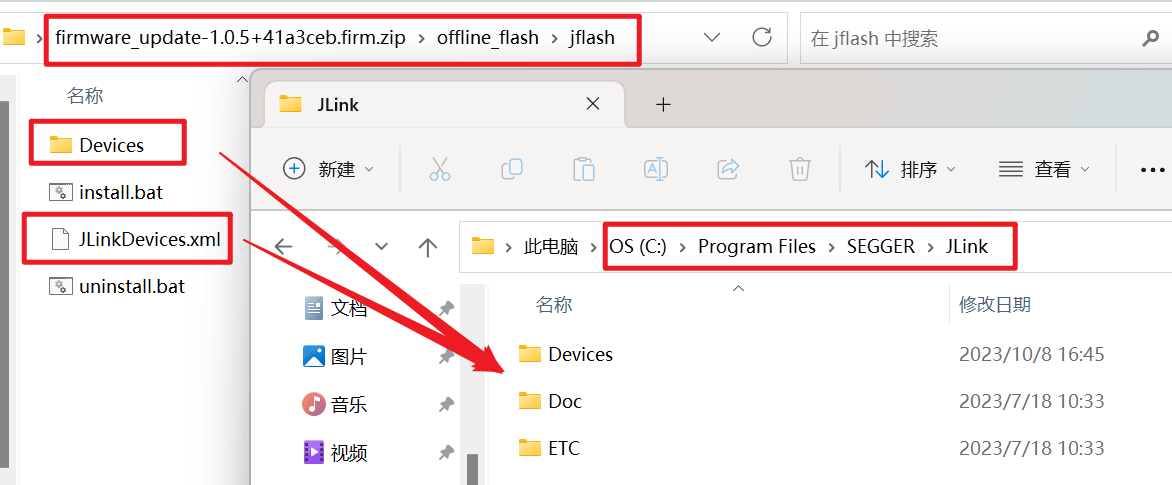
Remark: For the
.hexfile and “Firmware Correspondence Table”, see “Appendix 3: Firmware Correspondence Table”.
Hardware Connection
Connect to the robot arm joint interface. The connection interface locations of each joint differ slightly for different robot arms. For details, see “Appendix 5: Robot Arm Joint Interface Connection Locations”.
The connection interfaces of different controller models differ slightly. For details, see “Appendix 4: Controller Interface Board Flashing Locations”.
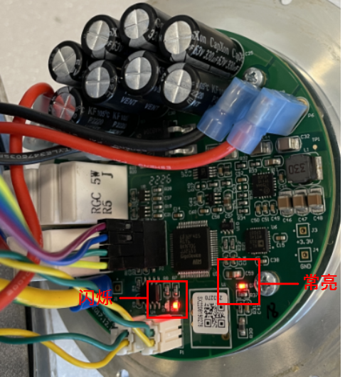
When the J-Link connection cable is connected properly, two indicator lights on the chip will light up: one indicator stays on, and the other indicator flashes. If at least one indicator light does not turn on, check whether the connection cable is normal.
After connecting the controller to the laptop with the J-Link connection cable, check whether the software driver was installed successfully.
Procedure
Open the J-Flash software.

Create a new project. Select [Create new project] and click [Start J-Flash].

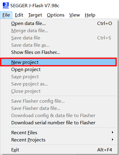
If the above pop-up window does not appear after opening the software, click [File > New project] to create a new project.
Click the icon in the [Target device] field.

The following figure uses an S series controller as an example. In [Device], enter the firmware chip model [STM32H7xx_W25Q64_S], select the chip found by the search, and click [OK].
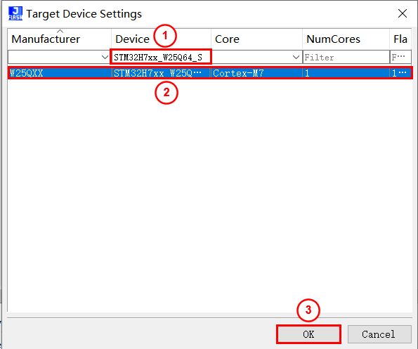
Click [OK].

Click [Target > Connect] to connect. After the connection succeeds, Connected successfully is printed in [Log].
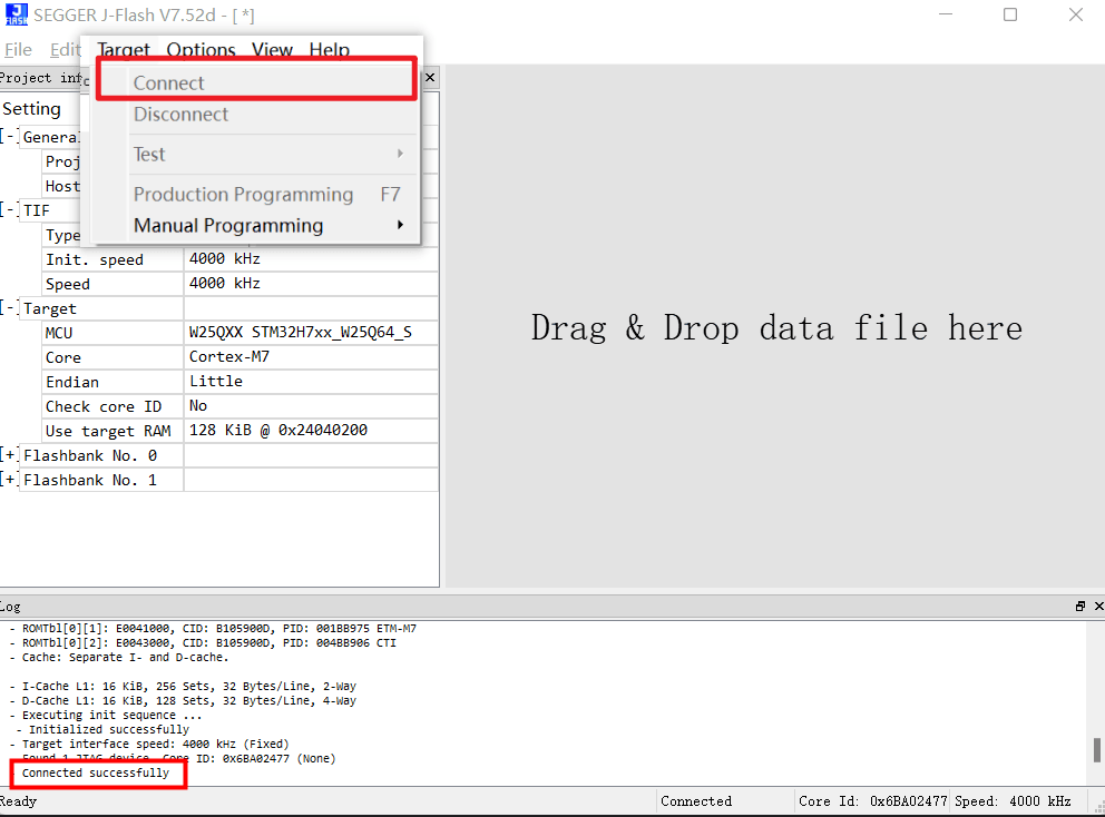
If J-Link is connected to an S controller and the controller is powered on, the power indicator of the S controller will automatically turn off after J-Flash connects successfully. This is normal.
To avoid data loss during the update, back up the data first. Click [Target > Manual Programming > Read back > Entire chip] to start reading data.
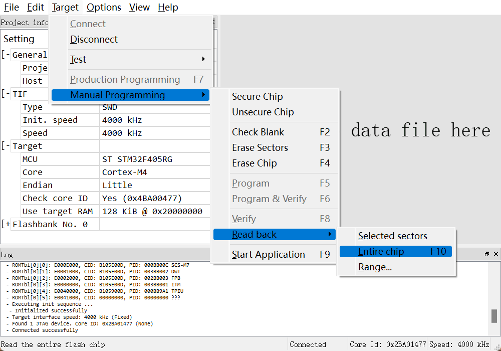
After data reading is complete, the following prompt appears. Click [OK] to return to the J-Flash screen.

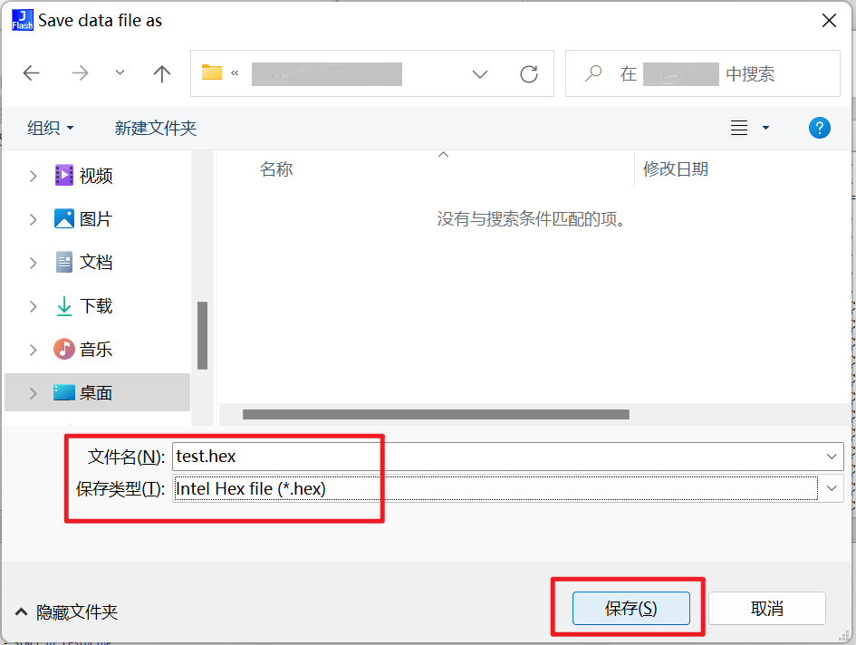
Press the shortcut keys [Ctrl] + [S] to save the read data, customize the file name, select “.hex” as the file suffix, and click [Save] to complete the backup. Click the cross in the upper-right corner of the J-Flash screen to close the data backup file.
Click [File > Open data file].
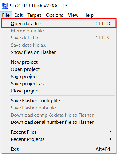
Select the
.hexfile to be flashed in thefirmware_update-xxx\offline_flash\apppath. The following figure uses an S series controller as an example. Select [controlbox_S_h100-1.0.30+c51e2c0.hex] and click [Open].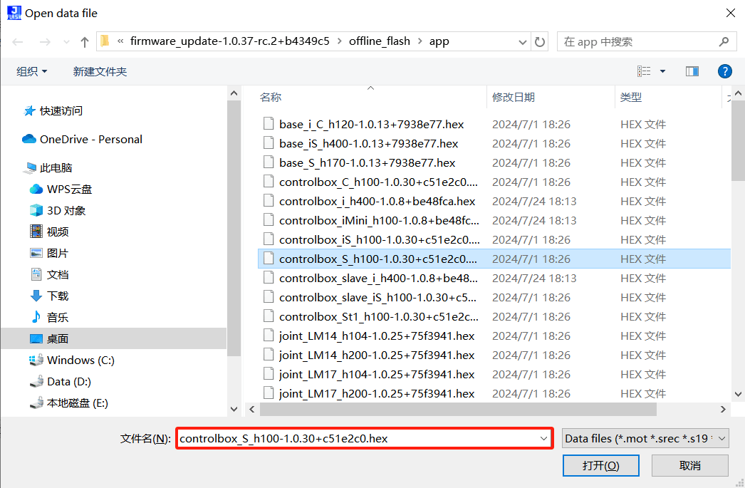
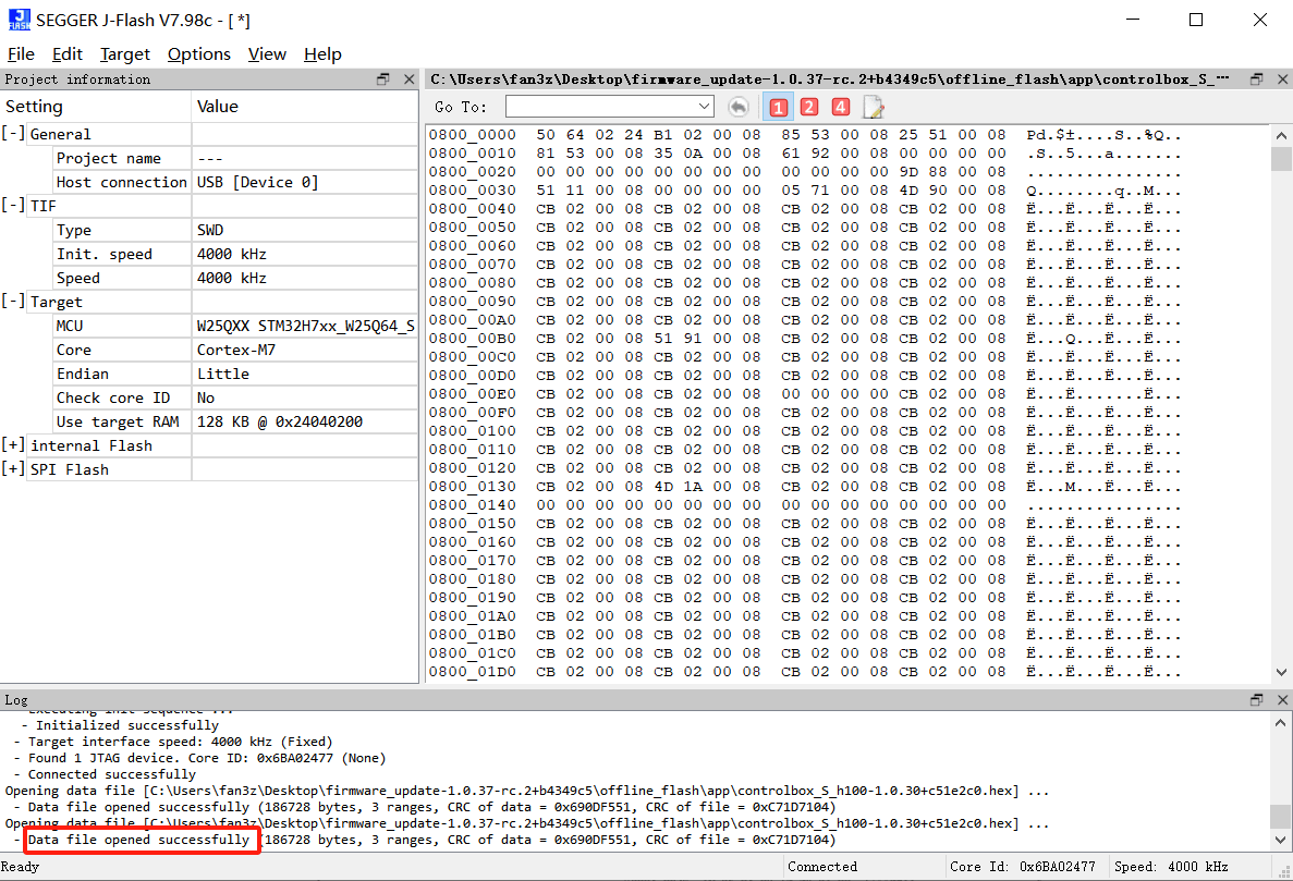
After opening succeeds, Data file opened successfully is printed in [Log].
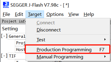
Click [Target > Production Programming] to start flashing.
After flashing is complete, the pop-up window shown below appears. Click [OK].

Click [Target > Manual Programming > Start Application] to run the written application.
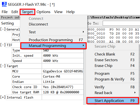
After the application runs successfully, Target application started is printed in [Log].
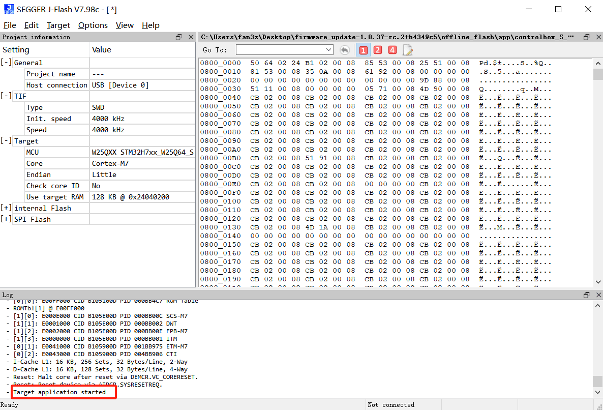
The J-Flash software automatically disconnects. If J-Link is connected to an S controller and the controller is powered on, the power indicator of the S controller will automatically turn on after J-Flash disconnects successfully.
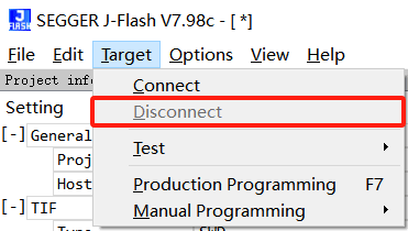
If step 12 is not performed, click [Target > Disconnect] to disconnect, and then restart the controller.
Click [Power On] on the home page of the teach pendant.
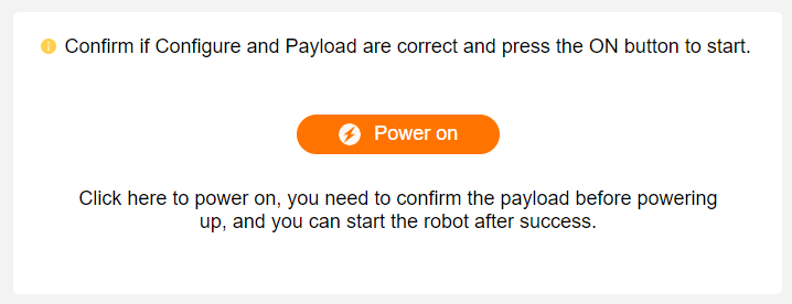
After the robot arm is powered on successfully, click [Robot Arm Information] to view the firmware version information. If the information is correct, the update is complete.
<img src="./pics/web-home-robot-infromation.jpg" style="width:45em">If the firmware version is not updated successfully, restart the controller and perform steps 14 and 15 again.
3.2.2 Offline Downloader
AUBO reminds users:
This operation will affect the robot zero coordinate and will not back up data. Operation failure will cause robot system abnormalities and require return-to-factory repair. If you need to perform this operation, contact technical support personnel. Unauthorized operation is strictly prohibited.3.3 Firmware Version Recovery
If problems occur after the firmware version is upgraded and you need to restore the firmware version to an old version, use the previously backed-up data file to flash again.
3.4 Common Firmware Flashing Problems and Solutions
3.4.1 Flashing Program Failed
Problem details: During the procedure in “3.2.1 J-Link”, step 6 (connecting the flasher) has been completed. In step 10, when flashing the program, a pop-up error appears:


Solution:
Solution 1: Reduce the flashing program speed
Set SWD "Init. speed" and "speed" to 1000 kHz.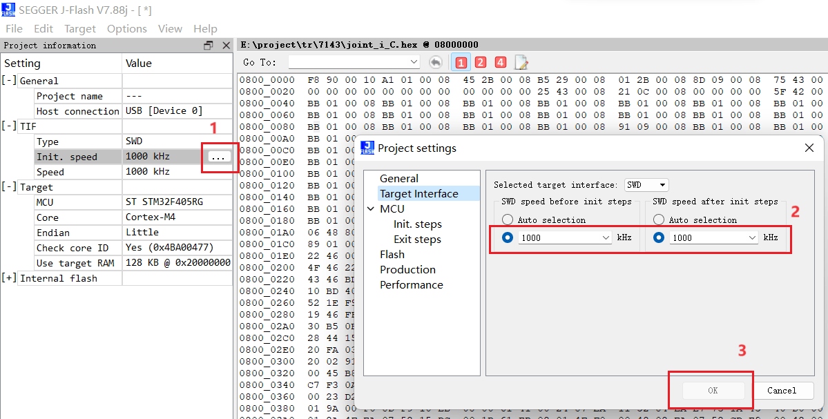
Solution 2: Increase wire transmission speed
If the flasher wire is long, shorten the wire.
3.4.2 After Using J-Link to Flash the S Controller Mainboard Firmware, the Power Light Does Not Turn On When the POWER Button Is Pressed and Held
Solution: Check whether the J-Flash software is disconnected. After J-Flash connects successfully, the power light does not turn on when the POWER button on the controller is pressed and held. This is normal. After disconnecting J-Flash, press and hold the POWER button, and the power indicator will turn on.
3.4.3 How Do I Determine Whether J-Link Has Successfully Connected to the Robot Arm Base?
Solution: Taking a C3 robot arm as an example, after J-Link connects successfully, one indicator light stays on and one indicator light flashes, as shown below.
3.4.4 How Do I Obtain the Chip Model?
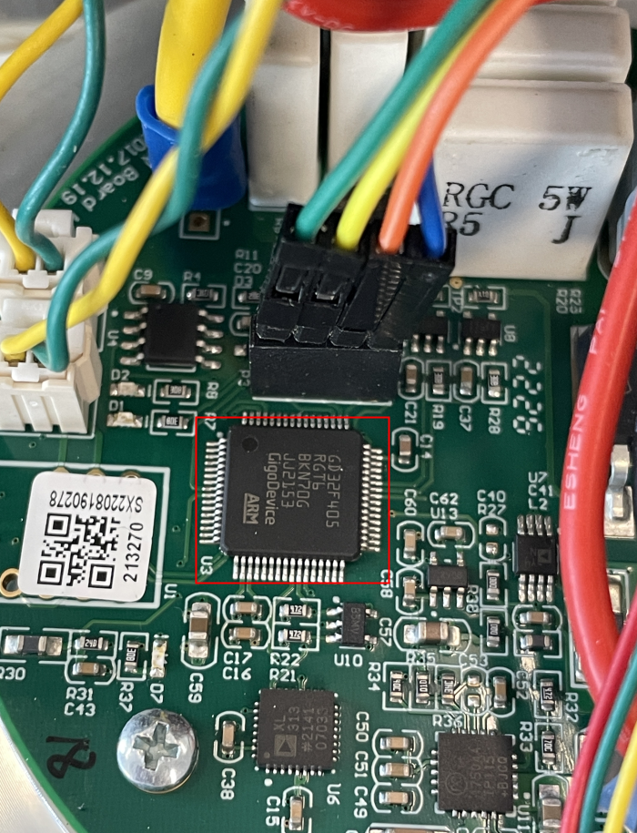
Solution: Check the chip marking. Taking a C3 robot arm as an example, the chip on the base is shown below. The base chip model is GD32F405RG. If you still have questions, contact technical personnel to obtain it.
Appendix 1: ARCS Software Version and Controller Model Correspondence Table
| Software Version | Controller Series | Remarks |
| arm | S Series Controller | 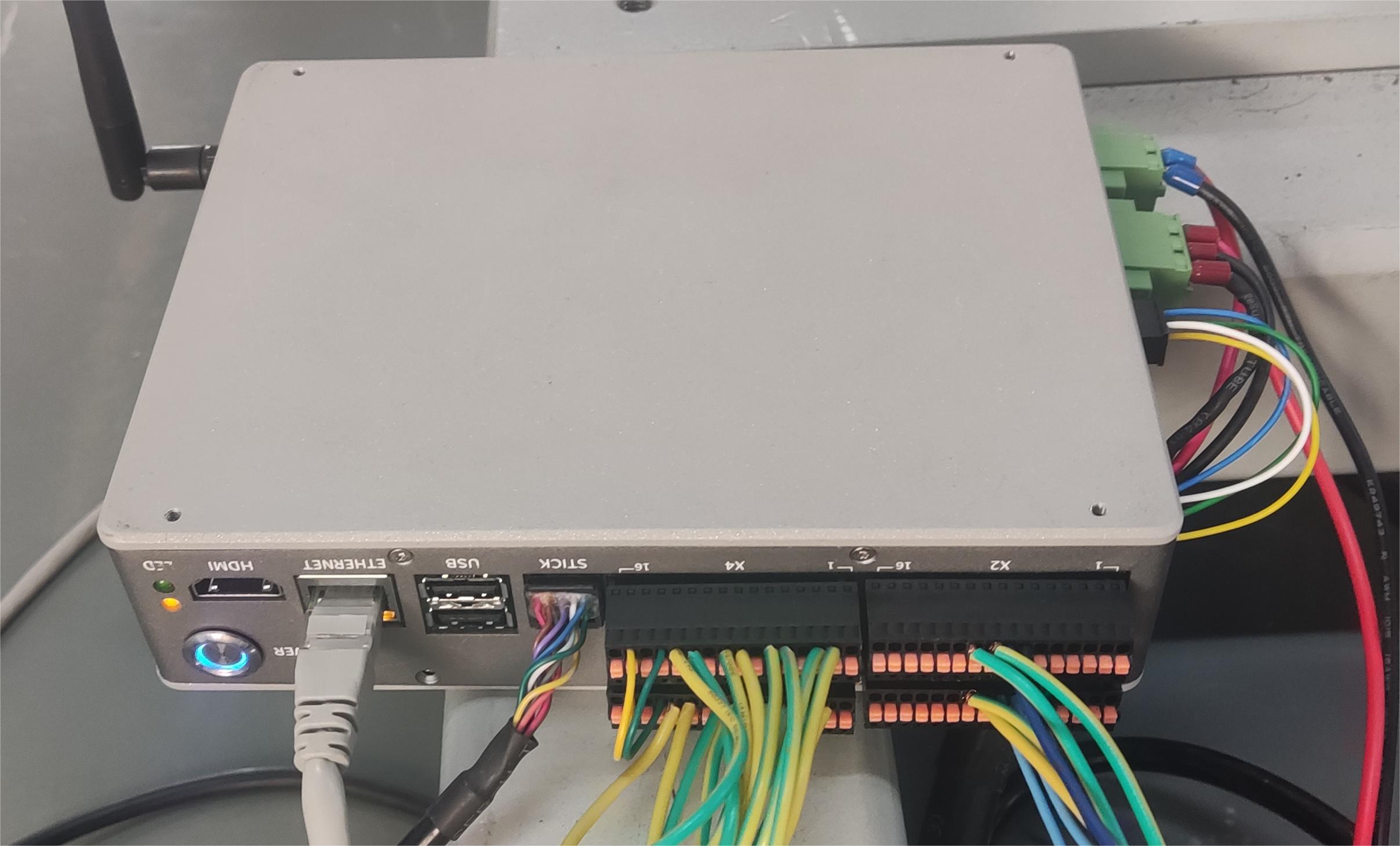 |
| x86 | Improved Controller | 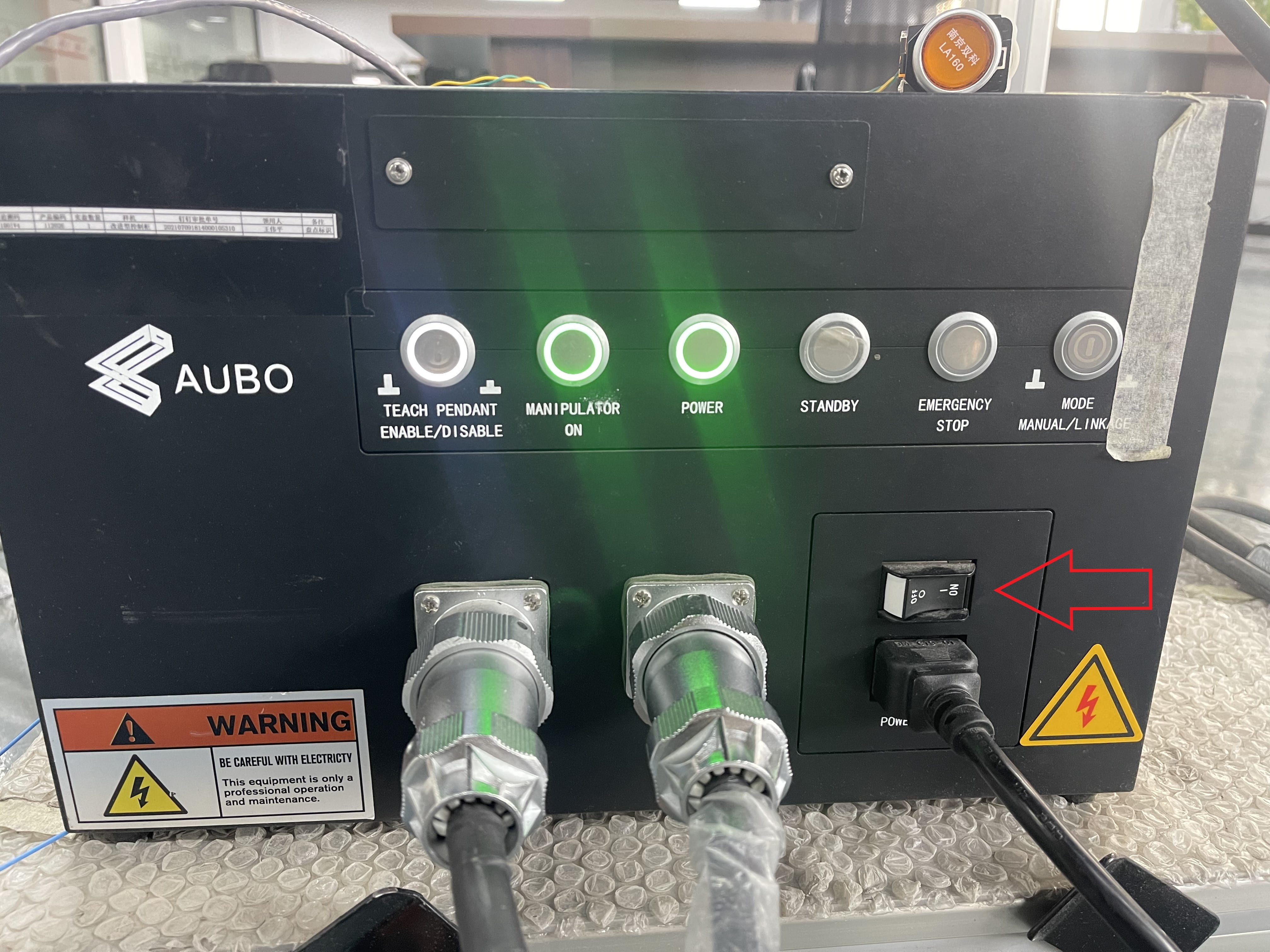 |
| iS Series Controller | 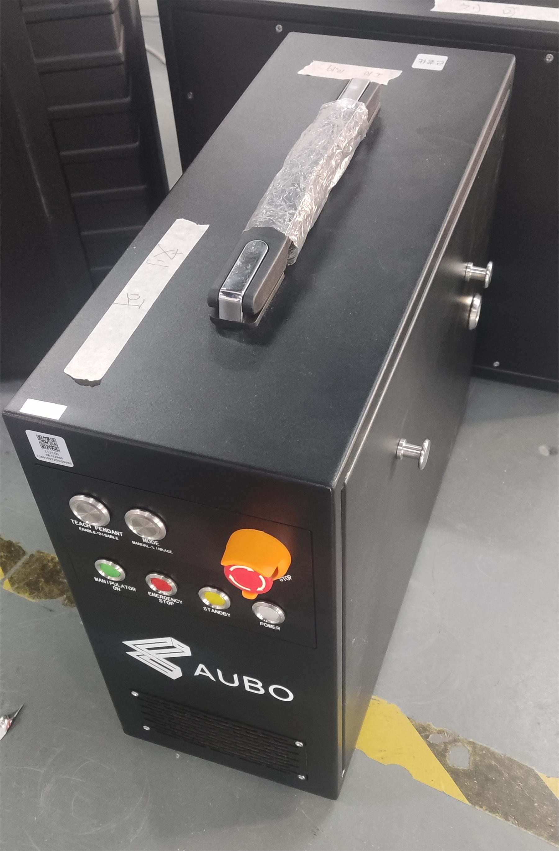 | |
| New C Series Controller | 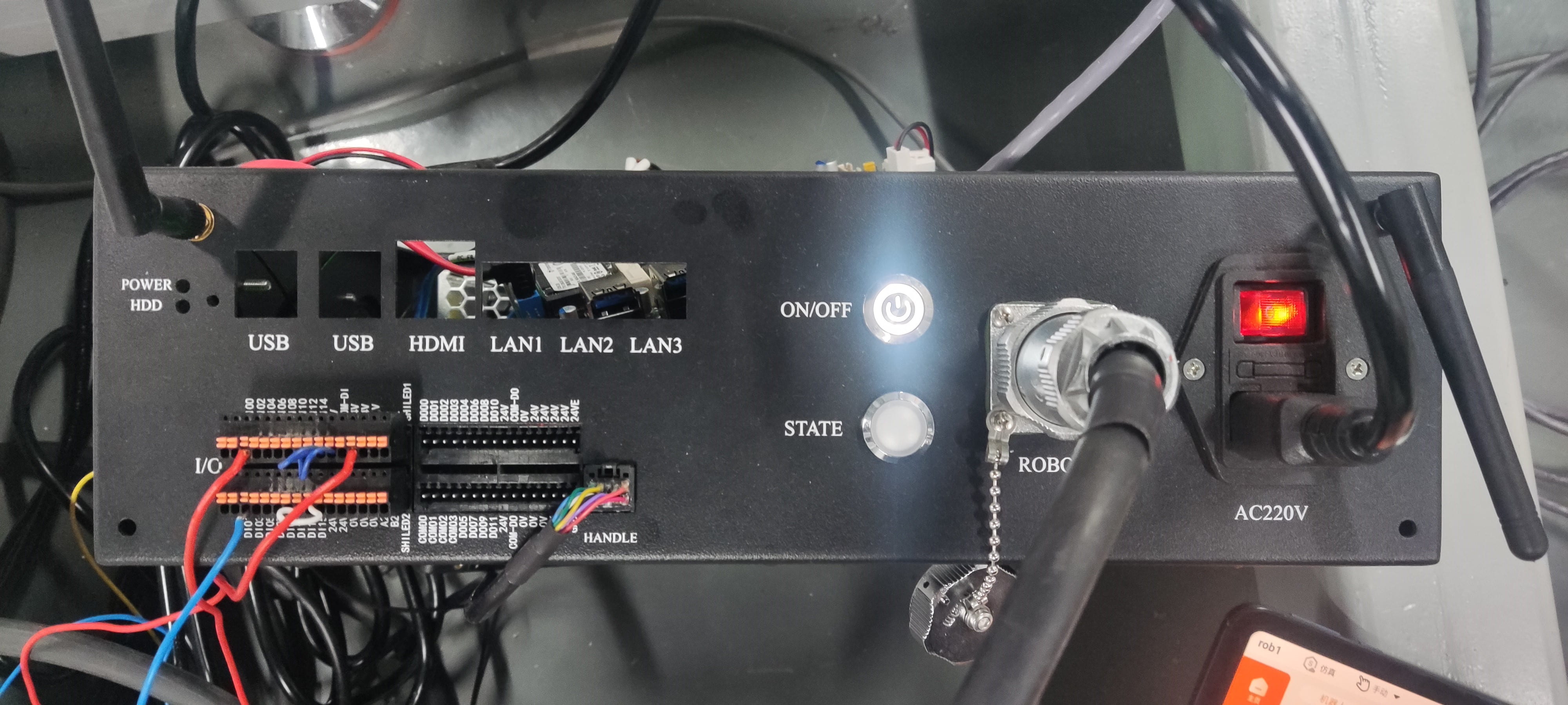 |
Appendix 2: ARCS Software Version and App Version Correspondence Table
| ARCS Software Version | App Version |
| 0.26 | 0.5 |
| 0.28 | 0.7 |
| 0.29 | 0.8 |
| 0.31 | 0.9 |
Appendix 3: Firmware Correspondence Table
The joint chip models corresponding to different series are as follows:
| Product Series | Joint Type | Chip Model |
|---|---|---|
| I, C Series | 14, 17, 20, 25 | STM32F405RG |
| I, C Series | 32, 40 | STM32F412RG |
| iH Series | 14, 17, 20, 25 | STM32F405RG |
| iH Series | 32, 40 | STM32F412RG |
| iS Series | 14, 17, 20, 25, 32, 40, 45 | STM32G431RB |
| S Series Single Encoder | 14, 17, 20, 25 | GD32C103CB |
| S Series Dual Encoder | 14, 17, 20, 25 | STM32G431RB |
| Humanoid | 11, 17, 20 | STM32G431RB |
| Integrated Servo | - | STM32F405RG |
Note: This table is for reference only. For more information about
.hexfiles and chip models, see the csv file in the firmware package. File path:firmware_update-a.b.c-xxxxxxx/config/output.csv
Appendix 4: Robot Arm Joint Interface Connection Locations
| Robot Arm Joint Model | Connection Interface |
|---|---|
| Regular Joint (C5 as an example) | 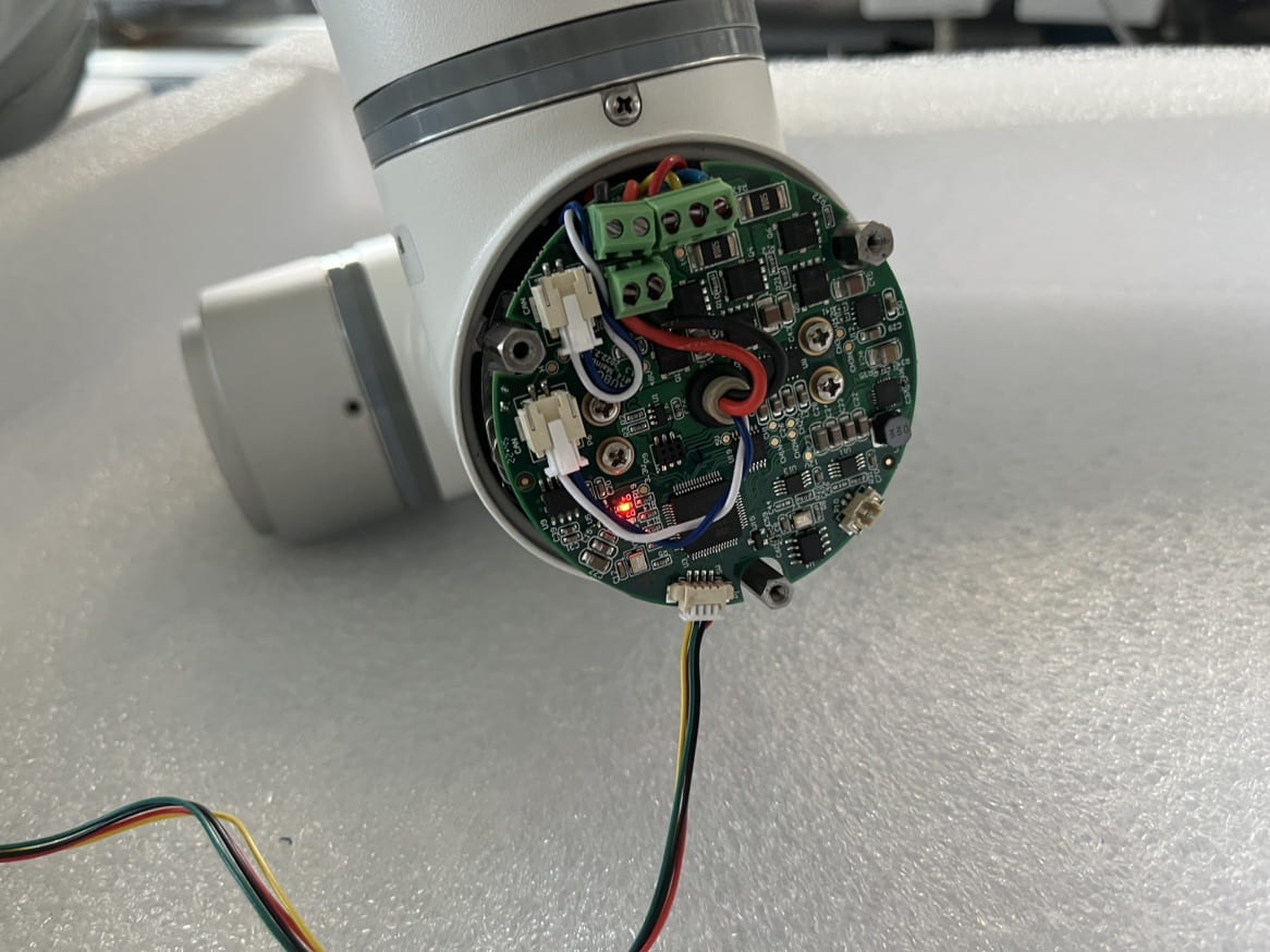 |
| iS series joints have master and slave chips. Only the bootloader program in the master chip is changed. | |
| iS Series 14 Joint(M14P) | -real.Bf4gYB2A.png) |
| iS Series 17 Joint(M17P) | |
| iS Series 20 Joint(M20P) | -real.CVDWDqci.png) |
| iS Series 25 Joint(M25P) | -real.BSL5f_vG.png) |
| iS Series 32 Joint(M32P) | -joint40(M40P)-real.BLkQr235.png) |
| iS Series 40 Joint(M40P) | |
Appendix 5: Controller Interface Board Flashing Locations
| Controller Model | Chip Flashing Port |
|---|---|
| AUBO-CB-M | 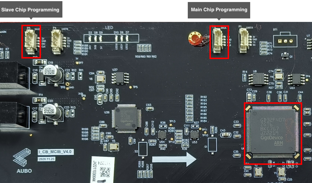 |
| AUBO-CB-AGV | |
| iS New Controller AUBO-IS-CB-M | 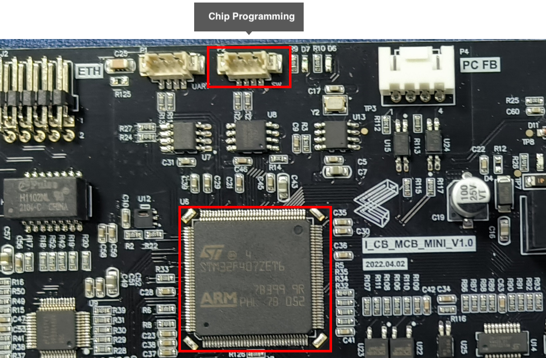 |
| Mini Controller AUBO-MINI-CB-M | 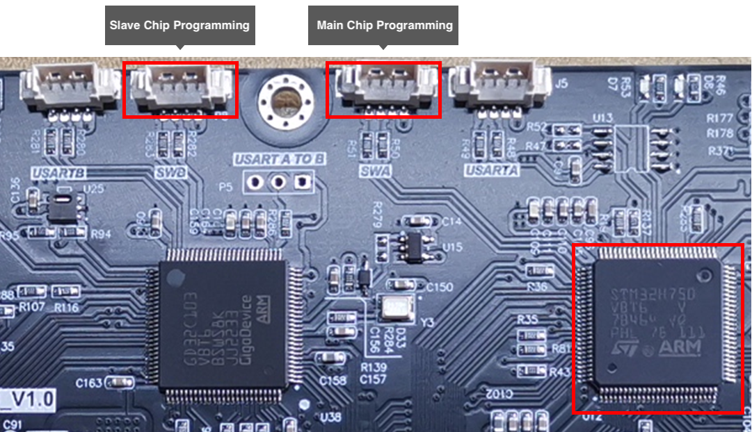 |
| Mini Control Box AUBO-MINI-CB-SM | |
| S-Main-Control | 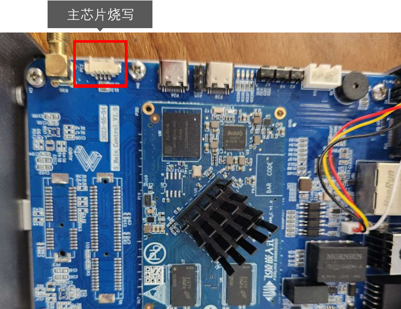 |