83 CAN Bus Error Troubleshooting Manual
Background
A CAN bus error may suddenly appear while the robot arm is running. Hardware troubleshooting requires hardware knowledge and dedicated tools. This manual describes preliminary troubleshooting from three perspectives: software, logs, and hardware.
Software Fix History
The upper-computer software has resolved most software bugs found during actual use and testing, including but not limited to:
- Data communication blocking
- Automatic checks for CAN and CAN FD
- Error reporting when transmitting an excessive number of bytes
Issue Categories
CAN bus error pop-ups generally have one of the following causes:
- Misoperation
- Version incompatibility
- Hardware problems
1. Misoperation
1.1 A “CAN bus error” appears after the firmware package is upgraded
The robot arm was running normally. The firmware was upgraded to resolve issues such as false collision alarms or failure to reach the target speed, and the error appeared after the upgrade. This situation is usually caused by an incompatible firmware upgrade package. Roll back the firmware version first to restore normal robot-arm operation, and then confirm with R&D whether an upgrade is required and which version should be selected.
2. Version Incompatibility
2.1 Background
The bootloader of the robot arm joint main-control chip was improved when it was upgraded from v1.0.x to v1.1.x. As a result, firmware cannot be upgraded directly from v1.0.x to v1.1.x.
The affected joint models are all models in the i series, C series, and iH series.
The affected base models are bases with the ROBOT POWER Board V1.2 silkscreen that use base_i_C_h120-*.hex firmware.
2.2 Solutions
- Use J-Link to download a firmware package containing the
v1.1.xbootloader, and then perform the online upgrade. - Upgrade the firmware to a
v1.0.xversion again to roll back tov1.0.x.
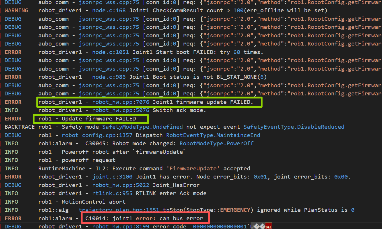
2.3 Related Log Output
When the firmware update fails in this situation, the log outputs the following message:
3. Hardware Problems
If on-site conditions permit, perform the preliminary hardware troubleshooting in the following sections. If troubleshooting is not possible or the cause remains unresolved, arrange return-to-factory repair and have R&D perform further analysis.
3.1 Phenomenon 1
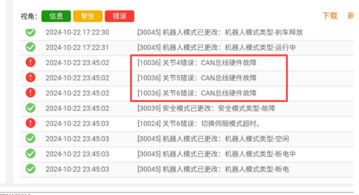
When a “CAN bus hardware error” may suddenly be reported during robot-arm operation, first check whether the cables are properly connected. If they are connected properly, the CAN wiring may have a problem—for example, the cable may loosen because of robot movement, or the fixing adhesive may loosen because of high temperature, making the CAN line unstable while the robot arm is moving.

3.2 Phenomenon 2
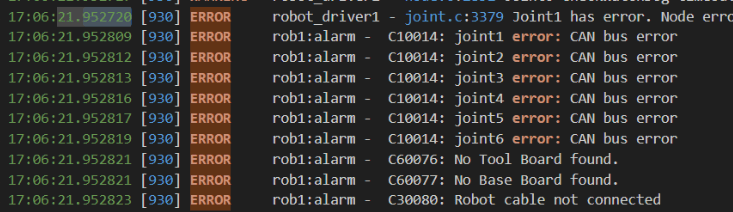
In this example, all six joints report errors, and communication with the tool board, base board, and robot is disconnected. This is also a typical hardware problem.
3.3 Phenomenon 3
When the robot-arm cable is too long, a “CAN bus error” may occur because of signal delay and instability.
3.4 Phenomenon 4
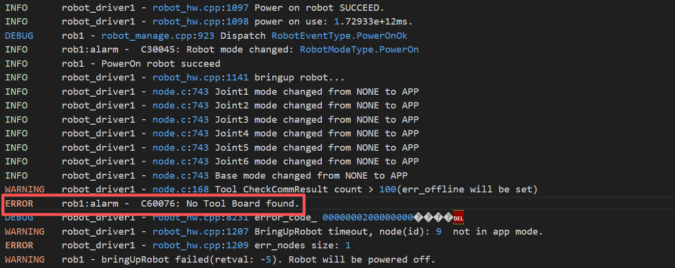
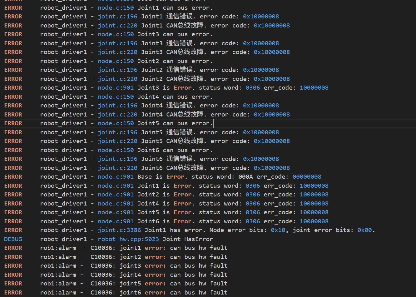
In this example, an error indicating that the tool board cannot be found is reported during power-on. This can also cause a “CAN bus error”.
3.5 CAN Line Damage Example
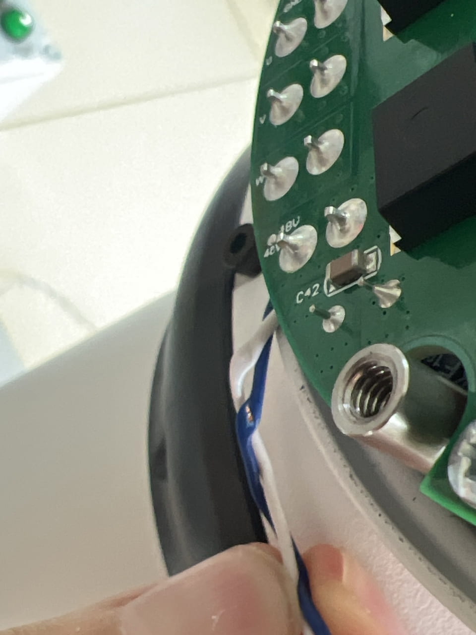
3.6 Detailed Hardware Troubleshooting
Note
If conditions permit, perform preliminary hardware troubleshooting on site according to the procedures below. If troubleshooting cannot be performed or the problem is still not located, arrange a return-to-factory repair and have R&D personnel perform further analysis.
3.6.1 CAN Bus Fault: Electrical Troubleshooting
3.6.1.1 Background
When a complete robot arm is taken off the production line and tested before delivery, its dielectric strength, insulation resistance, and system grounding must meet the applicable electrical safety standards. During testing, the following problems may be found: a motor winding shorted to the housing, the 48 V power supply shorted to the housing, or the CAN bus shorted to the housing. These problems degrade CAN bus signal waveforms and eventually cause CAN communication failures. A short circuit between CANH or CANL and the power supply or ground, or an incorrect termination resistance, can also cause a CAN bus fault. Therefore, perform electrical checks first when troubleshooting a CAN bus fault.
3.6.1.2 Test Equipment
Multimeter.
3.6.1.3 Test Items and Methods
- Measure the impedance between the power system and the robot-arm housing. Set the multimeter to resistance mode and keep the complete robot arm powered off. Measure the resistance between the housing and the 48 V positive terminal (red), and then between the housing and the 48 V negative terminal (black). A 1 MΩ resistor is connected in series between the joint reference ground and the housing; not every joint is actually fitted with this resistor. The measured resistance should be greater than
100 kΩ. If it is less than100 kΩ, or is only a few ohms, the 48 V power system has a short circuit or another fault to the robot-arm housing. - Measure the impedance between each joint winding and the robot-arm housing. Set the multimeter to resistance mode and keep the complete robot arm powered off. Measure the resistance between the housing and the U, V, and W motor windings of each joint. The measured resistance should be greater than
100 kΩ. If it is less than100 kΩ, or is only a few ohms, the insulation between a joint motor winding and the housing has failed. - Measure the impedance between the CAN bus and the robot-arm housing. Set the multimeter to resistance mode and keep the complete robot arm powered off. Measure the resistance between the housing and CANH, and then between the housing and CANL. The measured resistance should be greater than
100 kΩ. If it is less than100 kΩ, or is only a few ohms, the CAN bus has a short circuit to the housing. - Measure the CAN bus termination resistance. Set the multimeter to resistance mode and keep the complete robot arm powered off. Measure the resistance between CANH and CANL. The measured resistance should be
60 Ω: the120 Ωresistor at the control-cabinet end and the120 Ωresistor at the far end are connected in parallel. If the measured value deviates significantly from the target value, the termination resistance is abnormal. - Measure the CAN bus voltage. Set the multimeter to DC-voltage mode and power on the complete robot arm. Measure the voltage between CANH and system ground, and then between CANL and system ground. Each measured value should be approximately
2.5 V. A voltage that is too high or too low indicates a possible short circuit between the CAN bus and the system power supply or ground.
3.6.2 Analysis and Troubleshooting with a ZPS-CANFD Bus Analyzer
3.6.2.1 Background
A ZPS-CANFD bus analyzer can test and analyze analog bus-signal waveforms and messages. Compare the signal amplitude and noise to determine signal quality. If an electrical problem exists, an abnormal waveform can be observed in the waveform window. Filter and screen frames to quickly locate the bus problem.
3.6.2.2 Test Equipment
ZPS-CANFD bus analyzer or a bus analyzer from another manufacturer.
3.6.2.3 Test Items and Methods
Check whether the CAN signal waveform is normal. Confirm from the waveform whether the CANH and CANL signal amplitudes are correct and symmetrical, and whether the CANdiff (differential) level signal is normal.
The normal reference waveform is shown below:
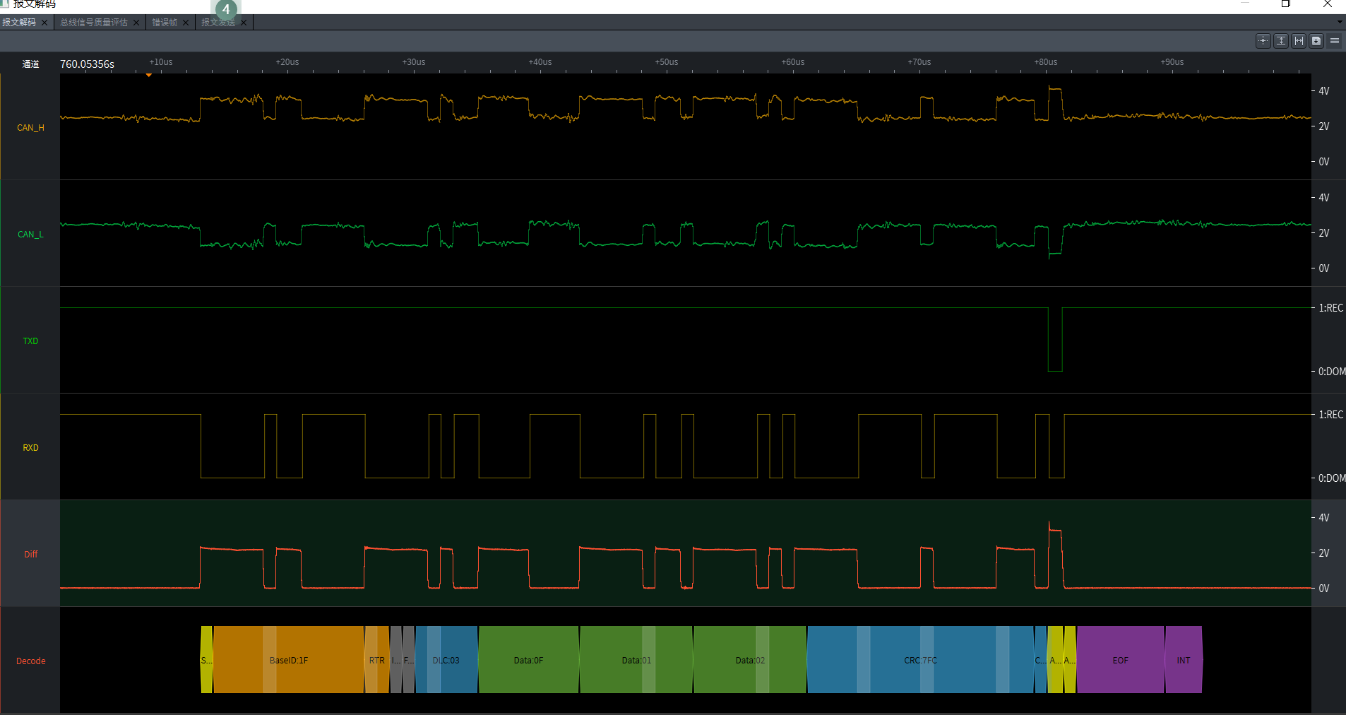
CANH and CANL should be symmetrical square-wave signals with normal voltage amplitudes. The Diff (differential) level signal should also be normal.
Filter and screen error frames. Analyze the captured bus data and filter or screen out error frames. Software personnel should further analyze the results and confirm the location of the bus problem.
3.6.3 Consistency of CAN Bus Node Configuration Parameters
3.6.3.1 Background
The products are currently transitioning from traditional CAN to CAN FD. Compared with a traditional CAN bus, CAN FD provides a higher transmission rate. The CAN transmission delay, sample point, and other configuration parameters of the base, joints, end, and other nodes must therefore be matched again. If an end node is not configured for CAN FD, joints 4, 5, and 6 may report a “CAN bus hardware fault”.
3.6.3.2 Test Equipment
ZPS-CANFD bus analyzer.
3.6.3.3 Test Items and Methods
- Confirm the complete robot arm's CAN bus type (standard CAN or CAN FD) from the upper computer.
- Confirm that the CAN bus configuration parameters of the base, every joint, and the end node are consistent.
- Use a ZPS-CANFD bus analyzer to identify the specific problem module. Filter error frames to locate the problem.
3.6.4 Quick CAN Bus Fault Troubleshooting
3.6.4.1 Background
This procedure is intended for production and test personnel to perform quick troubleshooting and locate problems.
3.6.4.2 Test Equipment
Adjustable 48 V power supply, CAN cables, and a joint of the same type as the joint that reported the error.
3.6.4.3 Test Items and Methods
- Replace the robot-arm aviation connector cable and test again. Use a standard-length cable of
5 m. - Rule out a CAN cable fault. Determine whether the robot arm uses a single CAN signal path or two CAN signal paths. For a single CAN signal path, replace the CAN cables in all joint center leads with new cables. For two CAN signal paths (one path for joints 1, 2, and 3, and one path for joints 4, 5, and 6), replace the CAN cable for the path corresponding to the error joint ID. For example, when ID 2 reports an error, replace the CAN cables for joints 1, 2, and 3. Power on the robot arm and check whether the fault is cleared. If the fault is cleared, test the CAN cable of each joint separately to identify and replace the faulty cable. If the fault remains, continue with the next step.
- Rule out a joint fault. Find a joint of the same type based on the error joint ID and set it to the same ID. Connect the CAN cable connected to the error joint to the replacement joint, and disconnect the CAN cable from the error joint. Connect the replacement joint to a 48 V power supply, power on the complete robot arm, and check whether the fault is cleared. If the fault is cleared, replace the joint. If the fault remains, replace the control cabinet and test the complete robot arm.
- If the specific cause is still not located, have R&D personnel troubleshoot the hardware problem.
3.6.5 CAN Bus Fault Waveform Reference
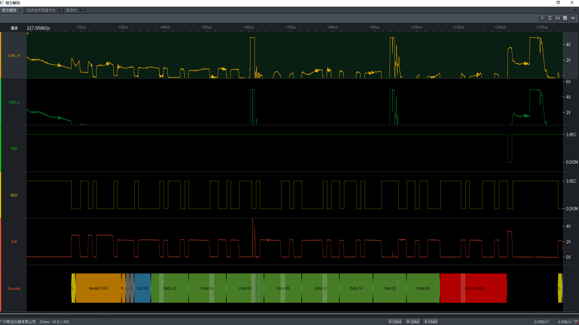
When a CAN bus has an electrical fault, the waveform window usually shows an abnormal signal amplitude, asymmetry, or differential level. The following is a reference example:
3.6.6 Capturing CAN Bus Data with ZLG ZCAN
Open the ZCANPRO software and select
USBCANFD-200Uas the device type.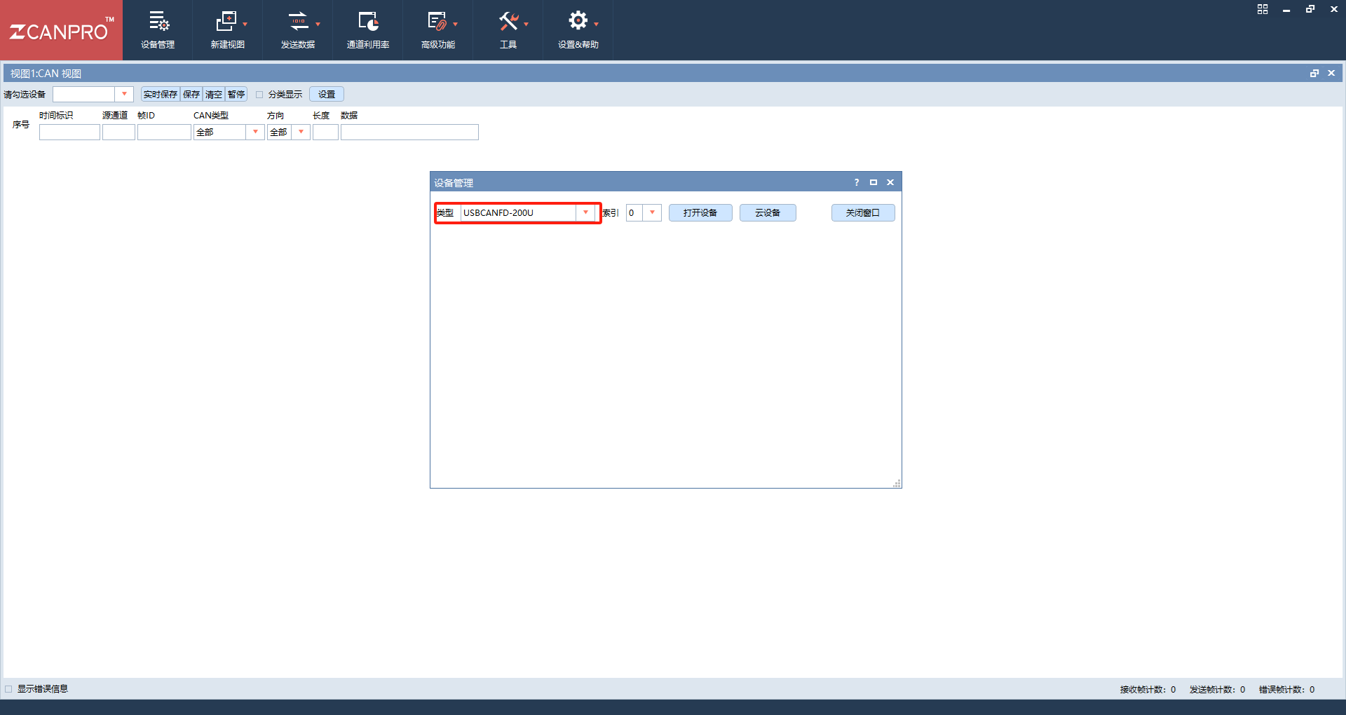
Click
Open Deviceand configure the parameters as shown. Set the arbitration-domain baud rate toCustom, and set the custom baud rate to1.0Mbps(75%),5.0Mbps(75%),(60,03800001,00800001); this value can be entered directly. SelectDisableorEnablefor the termination resistor according to the actual configuration. The default selection isDisable.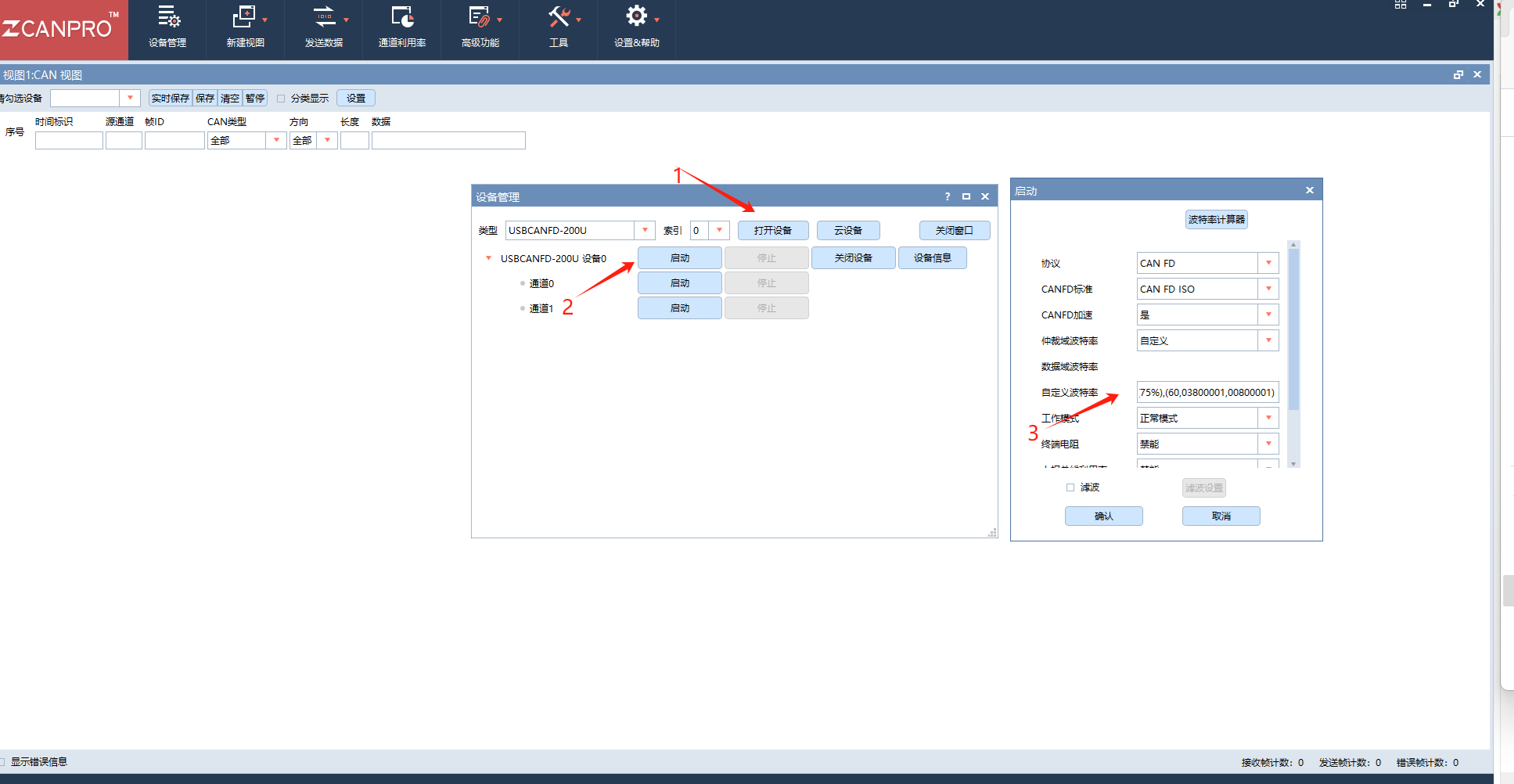
Click
Settings, set the time format toSystem Time, and set the maximum number of frames to100000(the maximum value). All parameters are now configured and CAN data can be captured.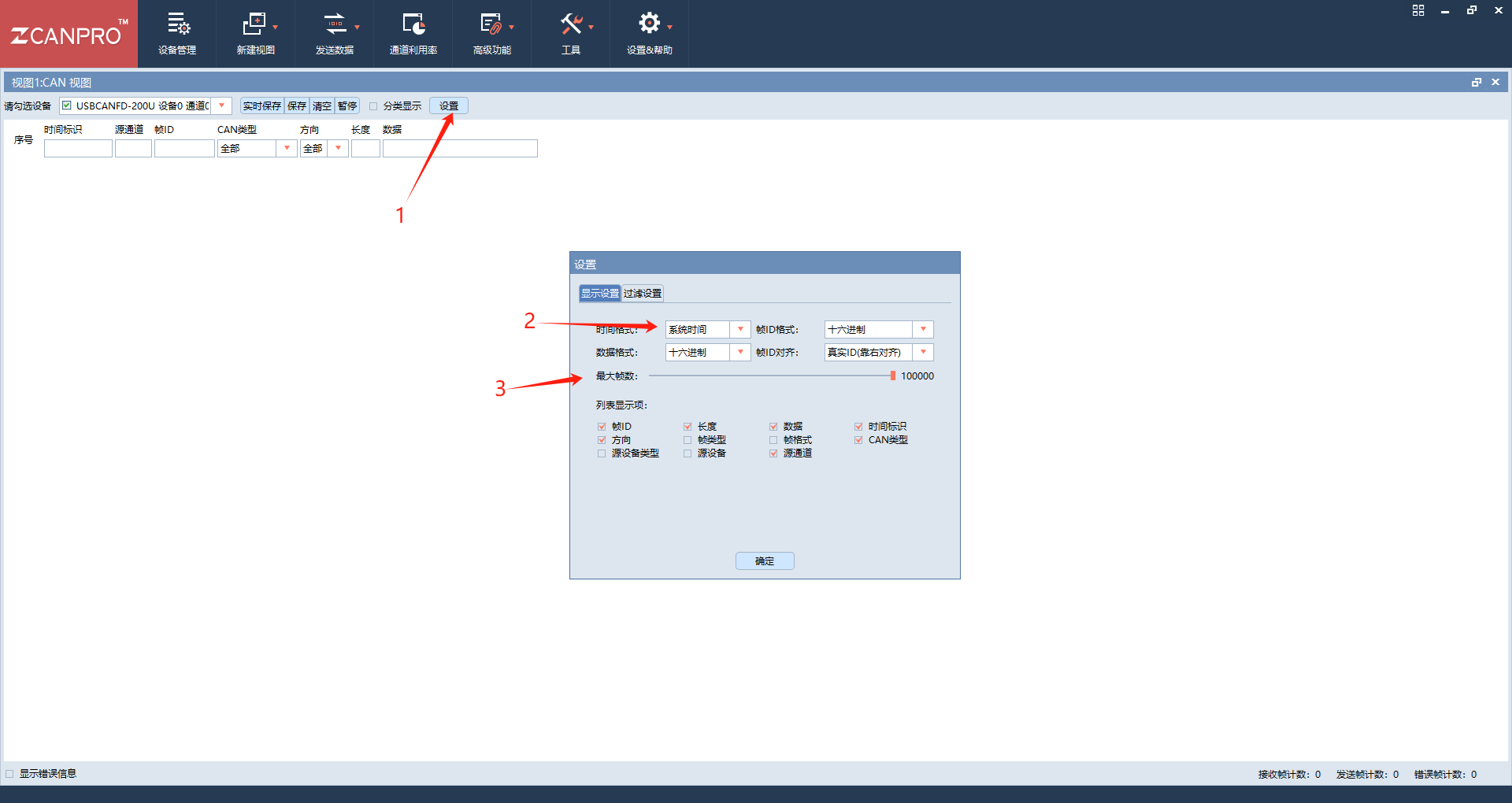
After capturing the data, click
Saveand save the data to the specified directory.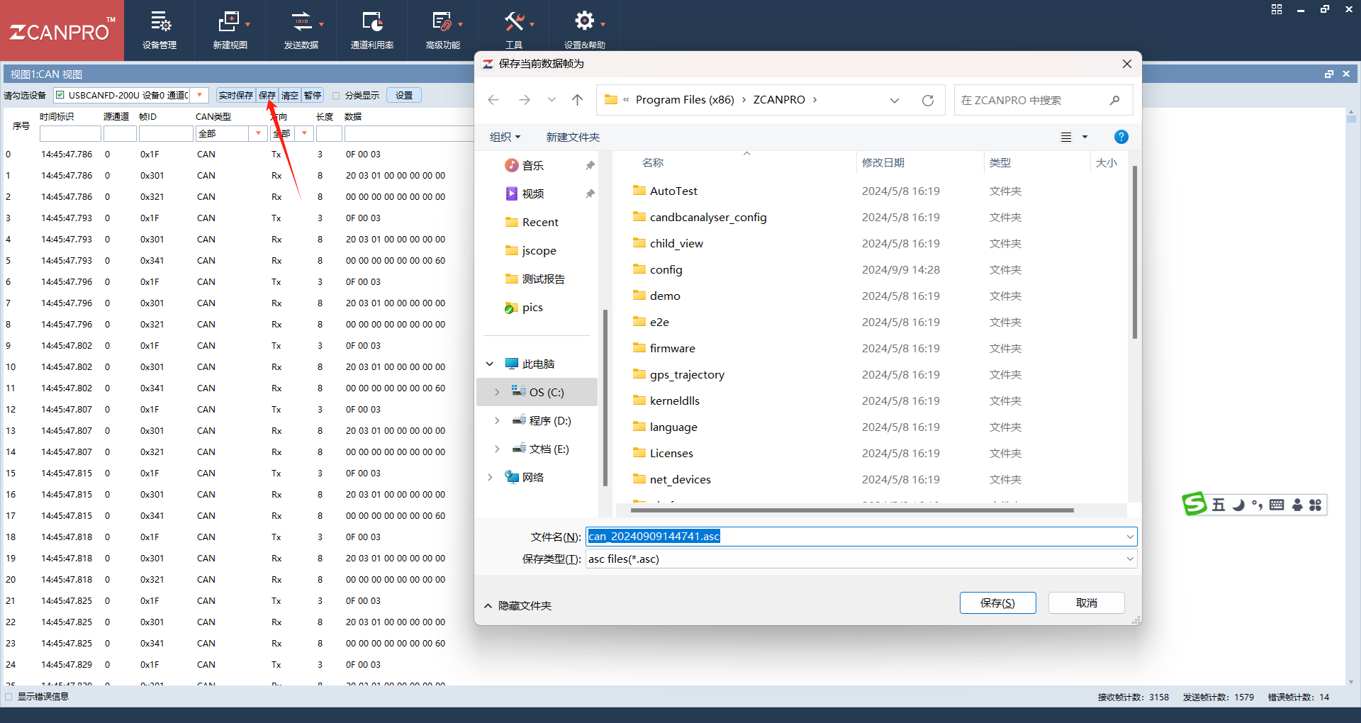
3.6.7 Single-Joint Testing Using CANLITE / PCANView and a ZPS-CANFD Bus Analyzer with the Robot Arm Forcibly Powered On
3.6.7.1 Background
A ZPS-CANFD bus analyzer can test and analyze analog bus-signal waveforms and messages. Commands are sent from the upper computer to test the signals of a single joint. Compare the signal amplitude and noise to evaluate signal quality. If electrical problems exist, abnormal waveforms can be observed in the waveform window.
3.6.7.2 Test Tools
- ZPS-CANFD bus analyzer.
- CANLITE upper computer (baud rate:
1 Mbps) or PCANView.
3.6.7.3 Test Method
- The CANLITE upper computer supports only a baud rate of
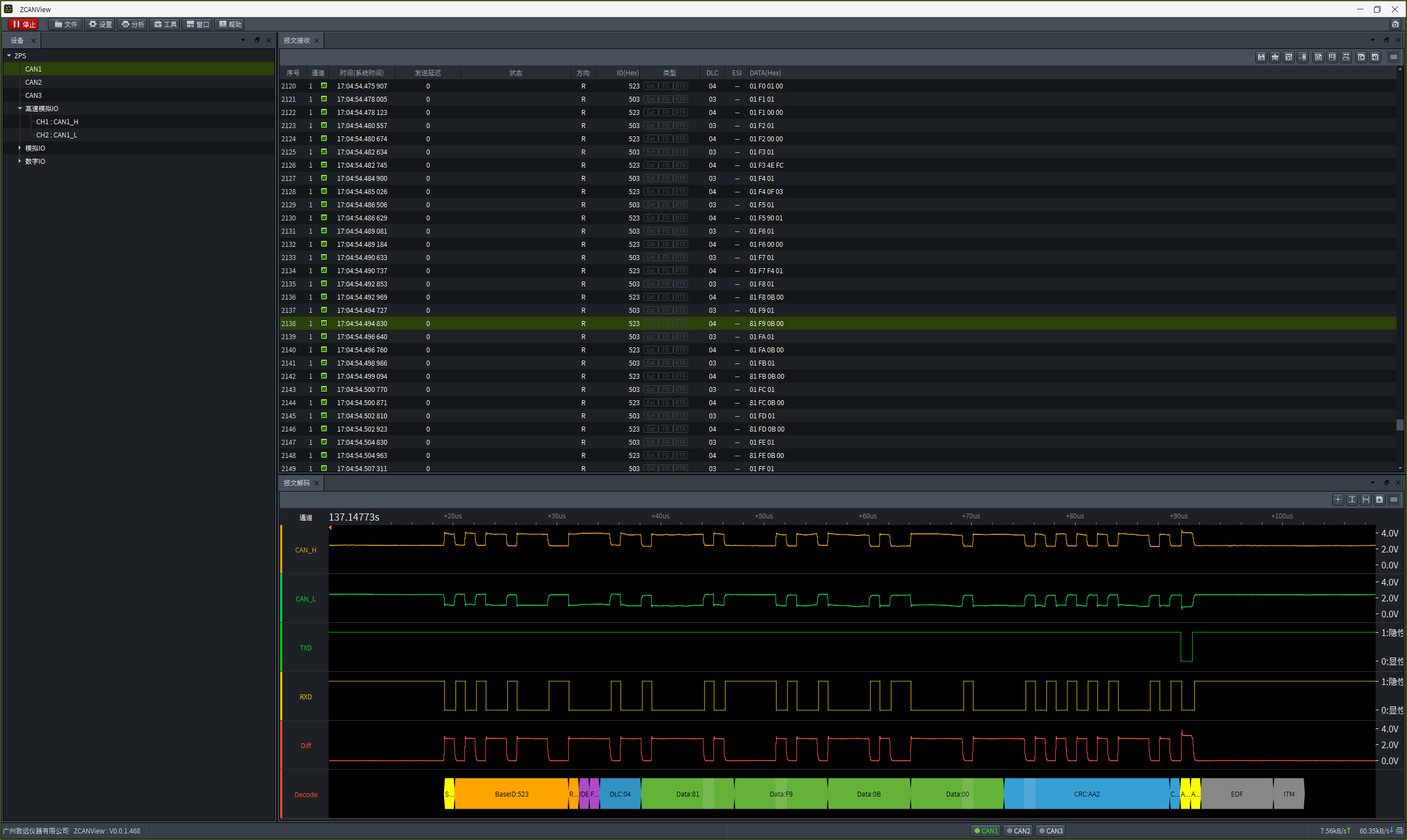
1 Mbps. At1 Mbps, use CANLITE to send the brake-release enable command, and then check whether the CAN signal waveform is normal. - At
500 kbpsor1 Mbps, PCANView can also be used. Send the servo enable command first, followed by the status read command, and then check whether the CAN signal waveform is normal.
The figure below shows normal CAN signal waveforms captured by the ZPS-CANFD bus analyzer after commands are sent using CANLITE or PCANView.
4. Log Error Code Classification and Analysis
/// Error codes
#define ERR_OVER_CURRENT_BIT    (((uint32_t)0x01) << 0) ///< Overcurrent
#define ERR_OVER_VOLTAGE_BIT    (((uint32_t)0x01) << 1) ///< Overvoltage
#define ERR_OVER_TEMPRATURE_BIT (((uint32_t)0x01) << 2) ///< Overtemperature
#define ERR_COMMUNICATION       (((uint32_t)0x01) << 3) ///< Communication
#define ERR_LOW_VOLTAGE           (((uint32_t)0x01) << 4) ///< Undervoltage
#define ERR_UVW_LOGIC_INVALID     (((uint32_t)0x01) << 5) ///< UVW logic invalid
#define ERR_UVW_ABZ_FAULT         (((uint32_t)0x01) << 6) ///< ABZ phase error
#define ERR_ABS_ENC_COMM_FAULT    (((uint32_t)0x01) << 7) ///< Absolute encoder error
#define ERR_ADC_ZERO_OFFSET_FAULT (((uint32_t)0x01) << 8) ///< ADC zero offset error
#define ERR_ENC_POLLUTE           (((uint32_t)0x01) << 9) ///< Encoder contamination level error
#define ERR_ENC_Z_LOST            (((uint32_t)0x01) << 10) ///< Z phase lost
#define ERR_ENC_CALI_FAULT        (((uint32_t)0x01) << 11) ///< Encoder calibration error
#define ERR_IMU_FAULT             (((uint32_t)0x01) << 12) ///< Inertial measurement unit fault
#define ERR_IPM_NTC_FAULT         (((uint32_t)0x01) << 13) ///< NTC fault
#define ERR_ABS_ENC_LOW_VOLT      (((uint32_t)0x01) << 14) ///< Absolute encoder low voltage
#define ERR_SHROT_CIRCUIT_FAULT   (((uint32_t)0x01) << 15) ///< Short-circuit fault
#define ERR_POS_OVER_LIMIT        (((uint32_t)0x01) << 16) ///< Position over limit
#define ERR_MOTOR_STALL           (((uint32_t)0x01) << 17) ///< Motor stall
#define ERR_ABS_MT_FAULT          (((uint32_t)0x01) << 18) ///< Absolute encoder multiturn fault
#define ERR_MOTOR_PHASE_LOSE      (((uint32_t)0x01) << 19) ///< Motor phase loss
#define ERR_BRAKE_FAULT           (((uint32_t)0x01) << 20) ///< Brake fault
#define ERR_REDUCER_OVER_TEMP     (((uint32_t)0x01) << 21) ///< Reducer overtemperature
#define ERR_REDUCER_NTC_FAULT     (((uint32_t)0x01) << 22) ///< Reducer NTC fault
#define ERR_FIRMWARE_UPDATE_FAULT (((uint32_t)0x01) << 23) ///< Firmware update error
#define ERR_FLASH_OP_FAIL         (((uint32_t)0x01) << 24) ///< FLASH operation fault
#define ERR_EXT_ABS_ENC_COMMFAULT \
    (((uint32_t)0x01) << 25) ///< Reducer-end encoder communication fault
#define ERR_BATTERY_LOW      (((uint32_t)0x01) << 26) ///< Battery low power
#define ERR_PHASE_ALIGN_FAIL (((uint32_t)0x01) << 27) ///< Lock magnet pole
#define ERR_CAN_BUS          (((uint32_t)0x01) << 28) ///< CAN hardware error
#define ERR_POS_CMD          (((uint32_t)0x01) << 29) ///< Position command discontinuity
#define ERR_POS_INIT         (((uint32_t)0x01) << 30) ///< Position initialization failed
#define ERR_TORQUE_SENSOR    (((uint32_t)0x01) << 31) ///< Torque sensor fault
4.1 Error Code Usage Example
The log reports the following error:

The log outputs error code 0x10000008. This value is hexadecimal. Convert it to binary and compare it with the error code list.
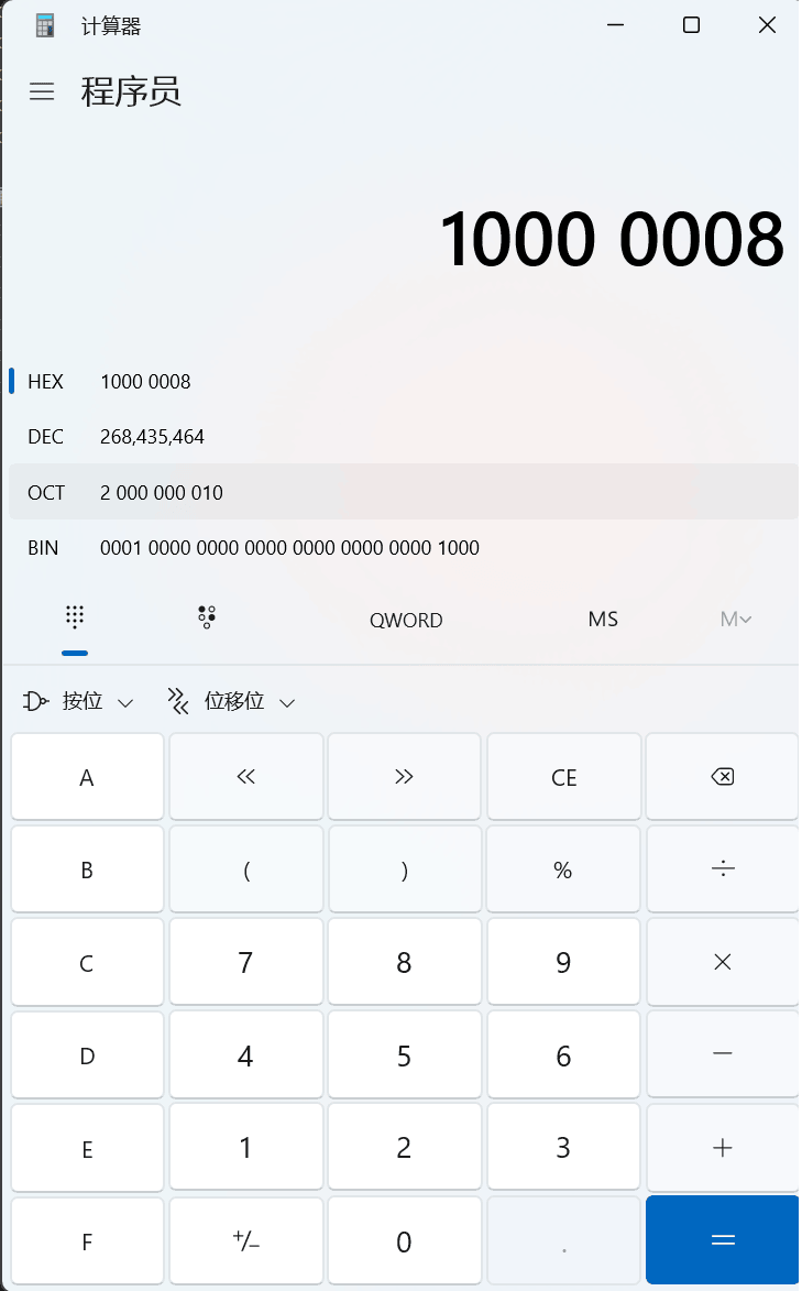
In binary, bit 3 and bit 28 have a value of 1 (counting from 0), which means:
- Communication problem
- CAN hardware error
If conditions permit, disassemble the robot arm and check the corresponding hardware. Otherwise, return the robot arm to the factory for repair.